Burner assembly instructions – Midco HMA-2 & HMA-2A Series User Manual
Page 18
Midco
®
International Inc. -
4140 West Victoria Street - Chicago, Illinois 60646 - toll free: 866 705 0514
tel: 773.604.8700 - fax: 773.604.4070 - web: www.midcointernational.com - e-mail: [email protected]
18
Printed in USA
8471 34
1113
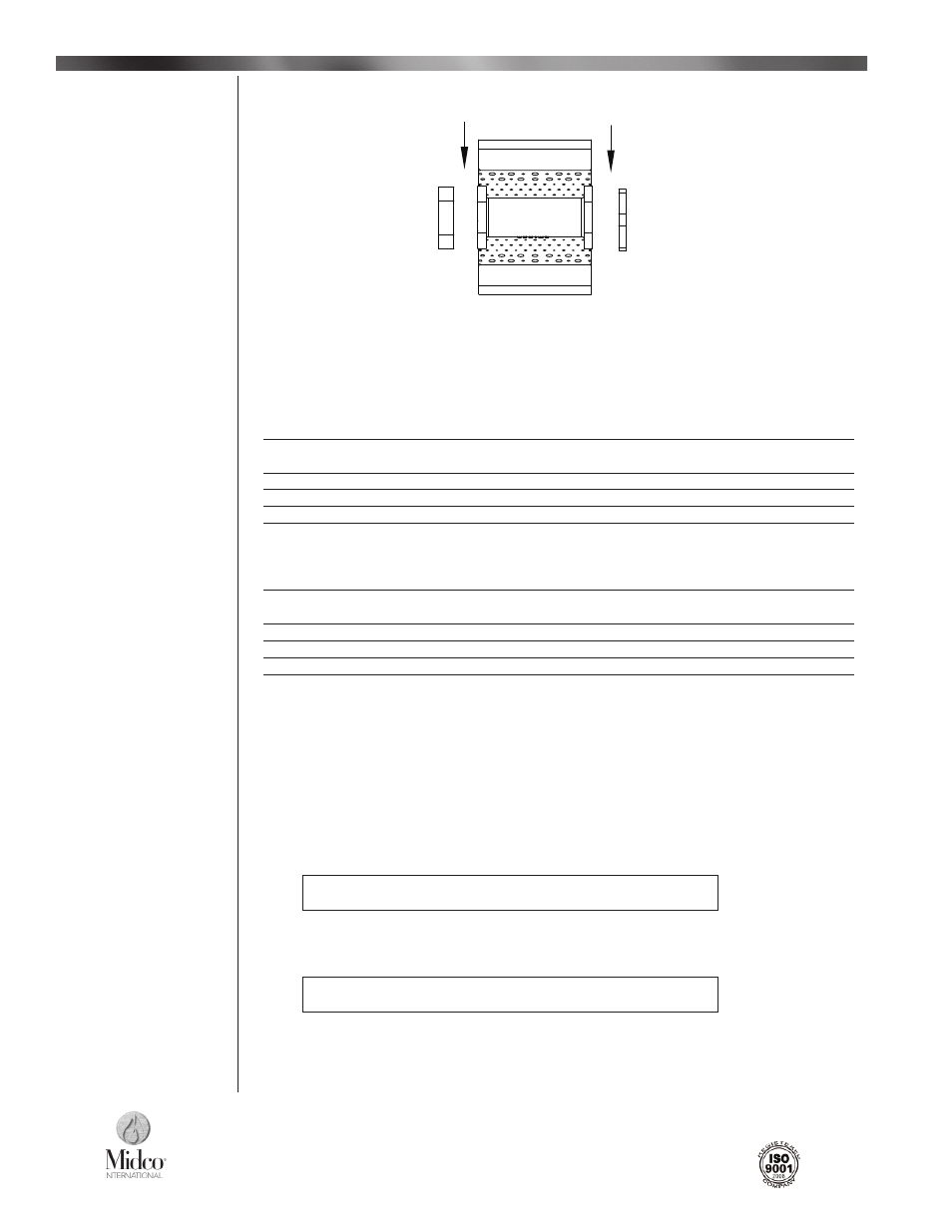
Figure 9 shows the assembly of a typical HMA 2 and HMA 2A direct fi red burner assembly for both
“in fi eld” and factory assembly line.
A) 1-1/2″ Inlet Flange With Pilot Mount or Blank Plate Hardware Required:
Furnace Cement
(See Notes # 1)
8 Stainless Steel Pcs of 10-24 X 3/8″ Slotted Round Head Screw,
10-24 Hex Nut, 10-24 Lock Washer or S62 Stainless Steel Rivet Body (Rivet Gun Required)
3 Pcs 5/16″ X 2″ Hex Cap Screws
3 Pcs 5/16″ Lock Washers
3 Pcs 5/16″-18 Nuts
B) Blank Flange With Blank Plate or Pilot Mount Plate Hardware Required:
Furnace Cement
(See Notes # 1)
8 Stainless Steel Pcs of 10-24 X 3/8″ Slotted Round Head Screw,
10-24 Hex Nut, 10-24 Lock Washer or S62 Stainless Steel Rivet Body (Rivet Gun Required)
3 Pcs 5/16″ X 1-3/4″ Hex Cap Screws
3 Pcs 5/16″ Lock Washers
3 Pcs 5/16″-18 Nuts
Notes:
1)
Furnace cement is to be applied between the casting and either blank plate, pilot plate and
end fl anges only, not between baffl es and end plates.
2) The hardware listed on instructions A and B applies to each end of any size burner with such
confi guration.
3) For defi nition and views of burner section, plates, fl anges, or hardware refer to page 16 and
17 of the Installation and Service Instructions manual.
4) Burner drawing symbols represent a view of the burner from side opposite the fl ame exit.
5) In the absent of a rivet gun, use the hardware specifi ed on these instructions, stainless steel
hardware is highly recommended.
UNDER NO CIRCUMSTANCES SHOULD STANDARD GRADE
OR ALUMINUM RIVETS BE USED.
6) Hardware used between burner sections is the same as the hardware used on Instructions B.
7) Pilot hardware Is Included with the pilot assembly.
8) If Installing mounting brackets, they must be Installed on the exterior side of the Inlet or blank
fl ange.
UNDER NO CIRCUMSTANCES SHOULD THEY BE INSTALLED
BETWEEN THE FLANGE AND THE BURNER CASTING.
___________________________________
Burner Assembly Instructions
A
B
Burner Assembly
Instructions
Figure 9 -
Typical HMA 2 & HMA 2A 6″ Direct Fire Burner Assembly