Packaging, wiring, and mounting, Packaging and pin assignments, Wiring – MagTek LOW POWER SHIFT-OUT User Manual
Page 14: Mounting, Table 1. signal and pin assignments – intellihead, Figure 2. low power shift-out intellihead wiring
Low Power Shift-Out IntelliHead
8
PACKAGING, WIRING, AND MOUNTING
Packaging and Pin Assignments
Signal and pin assignments for the Low Power Shift-Out IntelliHead connector (51021-0500) are
shown in Table 1.
Table 1. Signal and Pin Assignments – IntelliHead
Pin Number
Description
1 STROBE
2 DATA
3 VDD
4 GND
5 CASE
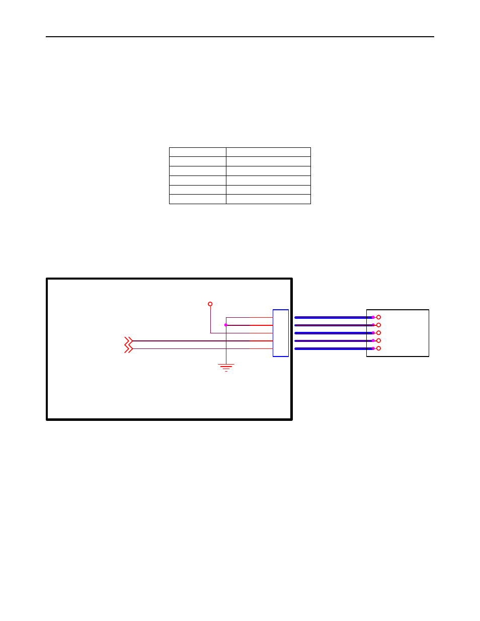
Wiring
The Low Power Shift-Out IntelliHead Wiring Diagram is shown in Figure 2. The recommended
mating connector
is Molex 53048-0510.
VDD
J1
1
2
3
4
5
DATA*
STROBE**
Head case ground shown connected to signal ground via the IntelliHead connector. It is better to
connect the head case ground directly to a separate earth ground if possible, bypassing the closely
spaced PCB connector terminals. If this is not possible, as is the case in many designs, then the
next best thing is to pass the earth ground through the board on its way to earth. Tying earth
ground to signal ground on the PCB is often done, but problems can arise in the case of extreme ESD
events.
Note that the signal
wires do not exit the
potting material of the
IntelliHead in the
orderly arrangement
implied above.
GND
VDD
DATA
STROBE
CASE
* The DATA line must be connected to an OPEN DRAIN OUTPUT/INPUT pin.
** STROBE must be an interrupt pin (or polled at least every 100ms) and tri-stateable.
For future compatibility with MagnePrint, the MCU must respond to the interrput and take
STROBE low within 25 us.
STROBE
DATA
VDD
GND
CASE
LOW POWER
SHIFT-OUT
INTELLIHEAD
CONTROLLER
CONNECTIONS
Flex cable or
discrete wires
HOST PCB
Figure 2. Low Power Shift-Out IntelliHead Wiring
Mounting
The Low Power Shift-Out IntelliHead drawing is shown in Figure 3.
Refer to the Reader Design Kit Specification, P/N 99821002, for complete mechanical mounting
information.