Cable connections and pin lists, Back sensor and card present, Track data – MagTek P-SERIES TTL User Manual
Page 13
Section 2. Installation
7
CABLE CONNECTIONS AND PIN LISTS
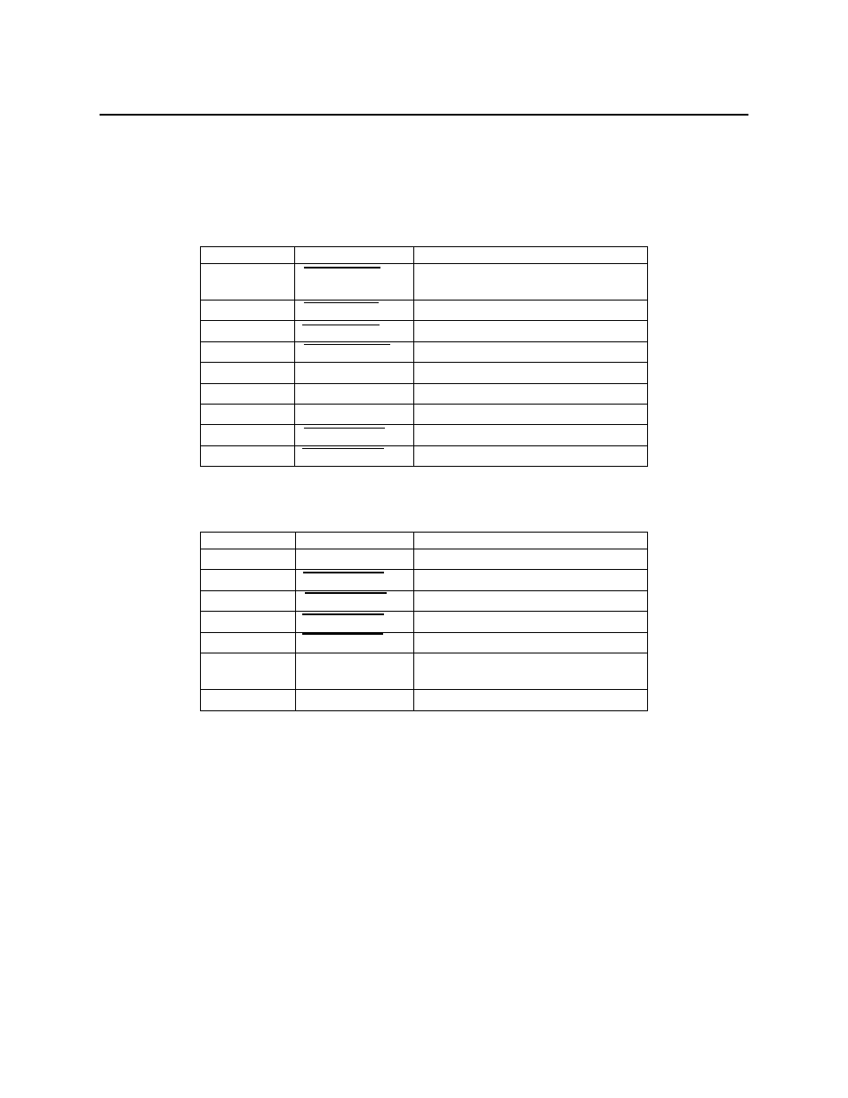
The cable connections to the host are J3 on the PCB. Table 2-1 lists the pins and signals for the
9-pin connector, and Table 2-2 lists the pins and signals for the 7-pin connectors.
Table 2-1. 9-pin I/O Header, J3, Pin List (P/N 21065114)
Pin Number
Signal
Description
1
Back Sensor
Active low when the card is at the
rear of the unit.
2
Track 2 Data
Active low
3
Card Present
Active low
4
Track 2 Strobe
Valid data with falling edge
5
Key
No Connection
6
Vcc
+5VDC
7
Gnd
Ground
8
Track 1 Strobe
Valid data with falling edge
9
Track 1 Data
Active low
Header: AMP P/N 640456-9
Mates: AMP P/N 640442-9 (one in a series of 50 – see AMP catalog)
Table 2-2. 7-pin I/O Header, J3, Pin List (P/N 21065117)
Pin Number
Signal
Description
1
Vcc
+5VDC
2
Track 1 Data
Active low
3
Track 1 Strobe
Valid data with falling edge
4
Track 2 Data
Active low
5
Track 2 Strobe
Valid data with falling edge
6
Back Sensor
Active high when the card is at the
rear of the unit.
7
Gnd
Ground
Header: ITW Pancon P/N MLAS100-7
Mates: ITW Pancon P/N CE100F28-7, CE100F26-7, CE100F24-7, CE100F22-7
Back Sensor and Card Present
The back sensor is active low when the card is fully inserted at the back of the unit. If a Card
Present signal is used as with P/N21065114 (See Table 2-1 above), the movement of an encoded
magnetic stripe past the read head generates the signal active low. These two signals are gated to
reduce the dwell time needed before the read-on-withdrawal can be initiated. On P/N 21065117,
Back Sensor is active high.
Track Data
Tracks 1 and 2 data signals are active low when data is read. See Timing below.