Section 2. installation, Connectors, Optional rs-232 cable – MagTek PORT POWERED User Manual
Page 13
7
SECTION 2. INSTALLATION
This section describes cabling information, mounting dimensions and PCB layout.
The installation consists of mounting the Reader and connecting the cable. The head may be on
top of the PCB, under the PCB, or if the unit has dual heads, both. The head, or heads, are
installed in the factory to customer specifications.
CONNECTORS
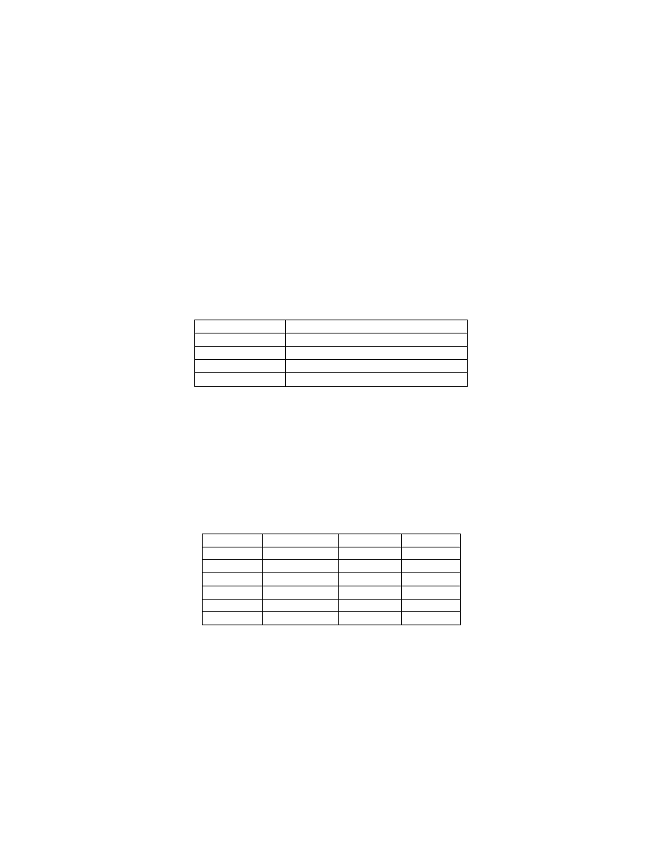
The connector pin list is shown in Table 2-1. The mating connector for J4 is Molex 51021-0400.
The terminals are Molex 50058-8000.
Table 2-1. J4 Connector - RS232
PIN NUMBER
SIGNAL (HOST AS REFERENCE)
J4-1
RXD (To PC)
J4-2
TXD (From PC)
J4-3
DTR (From PC)
J4-4
GND
All pins must be connected as shown.
OPTIONAL RS-232 CABLE
Optional serial cables, part numbers 21051499 (black) or 21041469 (white), are available. One
end connects to J4 and the other end is a DE-9 female. The pin list for the cable connectors is
shown in Table 2-2.
Table 2-2. Pin List for Cables 21051499 and 21041469
P1
SIGNAL
COLOR
P2
1
NC*
--
--
2
RXD
YELLOW
1
3
TXD
GREEN
2
4
DTR
ORANGE
3
5
GND
BROWN
4
6-9
NC*
--
--
All pins must be connected as shown.
*
NC = No connection