9 vcom communication protocol, 1 key and led layout – Videotec DCZ User Manual
Page 15
EN - English - I
nstruc
tions manual
13
9.1 Key and LED layout
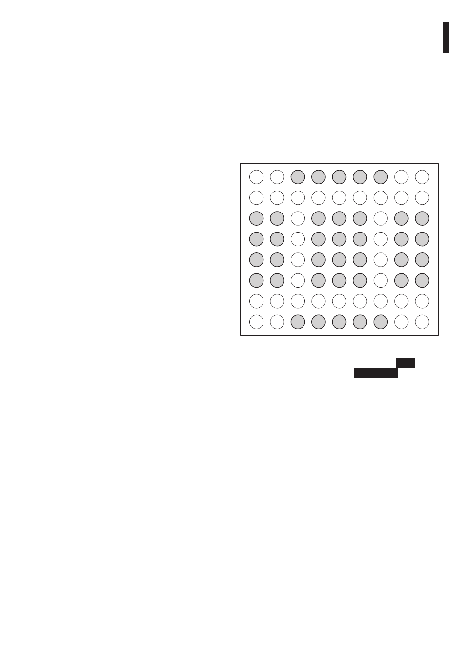
The DCZ keyboard manages a 72 key layout and the
corresponding LEDs (8 rows, each with 9 columns).
Regardless of the actual number of keys available
and used by the operator, each key/ LED coordinate
is always identified by the same 2 numbers: row (1..8)
and column (1..9).
When a key is pressed and released it transmits a
lookup chart value.
The lookup chart default values correspond to the
logical coordinates for each key:
11
21
31
41
51
61
71
81
12
22
32
42
52
62
72
82
13
23
33
43
53
63
73
83
14
24
34
44
54
64
74
84
15
25
35
45
55
65
75
85
16
26
36
46
56
66
76
86
17
27
37
47
57
67
77
87
18
28
38
48
58
68
78
88
19
29
39
49
59
69
79
89
Fig. 07
Example: On a default DCZ keyboard, the
ESC
key
is represented by code
13, the
MONITOR
key by
14, etc.
If the keyboard is rotated by 180°, the configuration
remains unaltered and there is no change from a PC
application point of view.
By changing the value associated to each key on the
lookup chart, it is possible to redefine its function and
to allow the user to use keys with the same value.
9 VCOM communication
protocol
When the keyboard is in VCOM mode it
communicates with the PC via a simplified ASCII
protocol. Printable characters are transmitted and any
numbers are transmitted as strings (not as decimal or
hexadecimal bytes).
No flow of hardware or software communication is
managed.
The PC application will open the serial port which
corresponds to the connected keyboard (the
baudrate and serial port configuration are irrelevant)
and it transmits/receives on this channel. The
keyboard responds to every command given by
the PC with an acknowledge message. Messages
transmitted by the keyboard do not require
acknowledgement by the PC application.