4 keyboard & alarm connector pin-outs – Videoswitch VQ-403C User Manual
Page 7
VQ-Series Real Time Splitter
User Manual
04/08/2004 17:25
Videoswitch 7 Vq601c.doc
3.3.1 Exit SETUP Mode
When you have finished configuration, press the ALT key and
key again to quit. All settings will be
saved, including the screen mode being displayed when this is done. If no keys are pressed for 30 seconds,
SETUP mode will automatically be terminated.
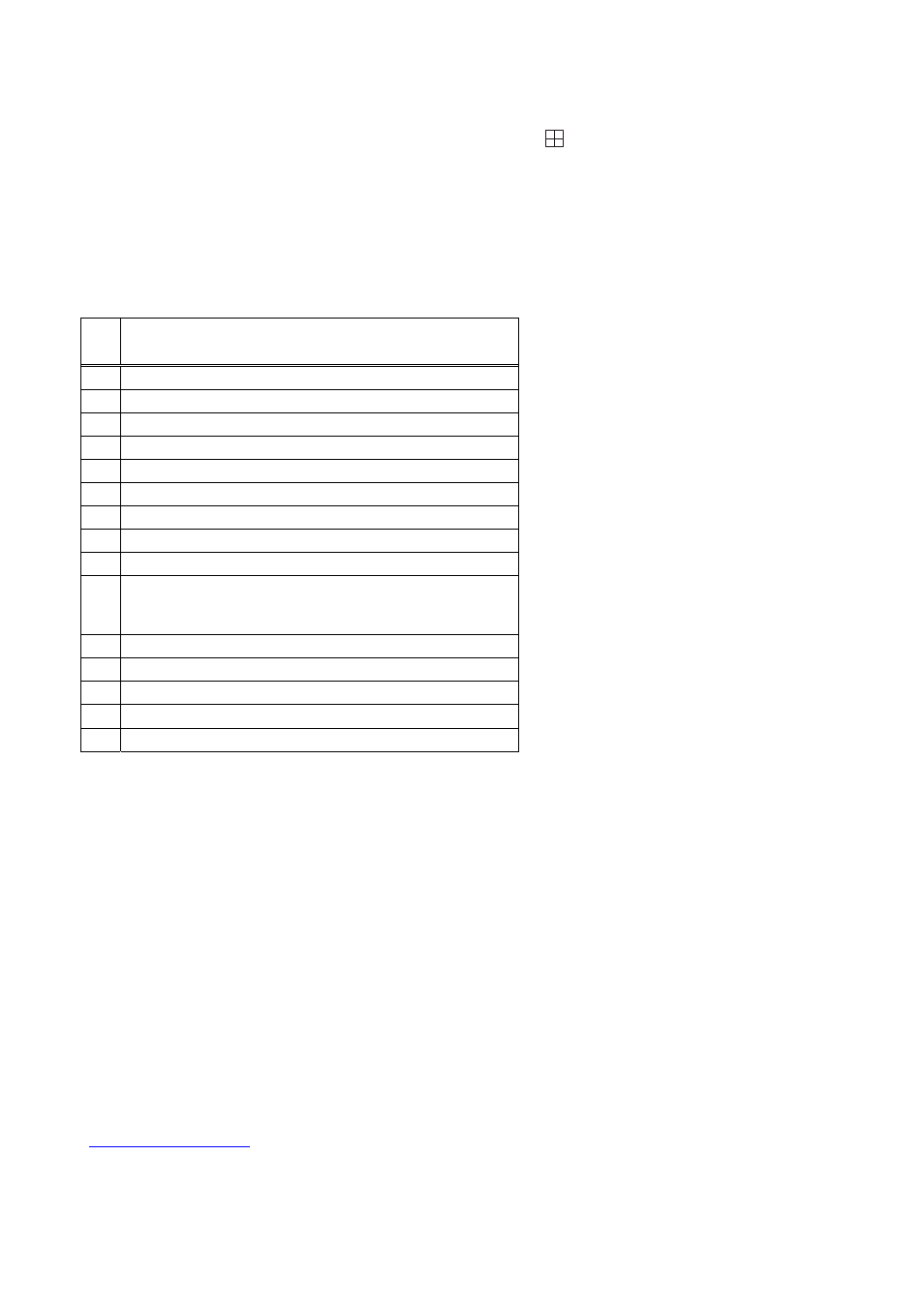
4 Keyboard & Alarm Connector Pin-Outs
Pin Description
1 Alarm
2
2 Alarm
4
3
Do not connect
4
Do not connect
5 Ground
6 Alarm
1
7 Alarm
3
8
Do not connect
9
Do not connect
10
Connect to Pin 15 to terminate the RS485 input unless
the twisted pair is being daisy-chained to another
terminated device.
11
Relay Normally Open
12 Relay
Common
13
Relay Normally Closed
14
Remote Keyboard Input (RS485+)
15
Remote Keyboard Input (RS485-)
For RS232 remote control:
• Connect Pin 14 to Pin 5
• Connect RS232 data (TXD) to Pin15
• Connect RS232 ground to Pin 5
The cable required for control from a PC with a 9-way D-type on its RS232 (COM) port is as follows:
PC
VQ-Series
Splitter
===
==============
3-----------------------------------15
|----------14
5------------------------|-----------5
The VQ-Series Splitter can be controlled using the PC “VDM-Remote”, available free of charge from
www.videoswitch.co.uk
.