1 installation, 2 operation, 1 connecting up – Videoswitch VQ-403C User Manual
Page 4: 2 termination, 1 power-up, 2 multi-screen selection
VQ-Series Real Time Splitter
User Manual
04/08/2004 17:25
Videoswitch 4 Vq601c.doc
1 Installation
1.1 Connecting Up
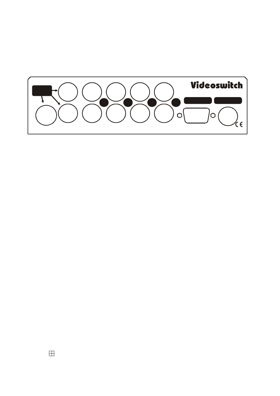
The diagram below shows the connector arrangement on the rear panel (unit viewed from rear). Note that
lettering for the camera numbers on the actual rear panel may be in error; this diagram shows the correct
numbering:
VQ REAL TIME SPLITTER
MONITOR
OUTPUTS
4
3
2
1
12V DC INPUT
KBD & ALARM
• Connect cameras to BNC inputs (1, 2, 3 and 4 lower row). If the unit is being used just as a two-way
horizontal or vertical splitter (VQ-403C only), connect cameras to inputs 1 and 2 only.
• If required, loop through cameras to other equipment (1, 2, 3 and 4 upper row)
• Connect monitor(s) to BNC and/or S-Video outputs.
• Plug in the 12V power supply to the 3-pin Mini-DIN connector.
• If alarms are to be used, connect normally open contacts KBD & ALARM connector (refer to section
4).
• If a remote keyboard is to be used, connect twisted pair to KBD & ALARM connector (refer to
section 4).
1.2 Termination
In normal use where the camera signals connect only to this quad, the four DIL switches under the unit
should all be ON.
If cameras are looped through to other equipment that terminates the video, then the corresponding DIL
switch sections should be turned OFF.
2 Operation
2.1 Power-Up
Plug the flying lead of mains power adaptor into the “+12V DC” power input connector. Plug the adaptor
itself into the mains supply.
2.2 Multi-Screen Selection
Press the
key to step through the available multi-screen modes.
The screen modes that are provided on the different models are: