High Country Tek Plug Top Driver Series User Manual
Page 9
C
o
m
m
a
n
d
S
ig
n
a
l 0
to
1
0
0
%
Output Current into Inductive Coil Load
Curve applies to:
• PTD-12-C
• PTD-12-V
• PTD-24-C
• PTD-24-V
Electronic Controller Solutions for the Fluid Power Industry
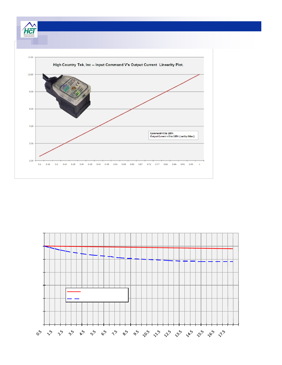
Product Operation Notes
Current set 600mA
High Country Tek, Inc PTD with Current regulation.
0
0.1
0.2
0.3
0.4
0.5
0.6
0.7
Time in Minutes
C
u
rr
e
n
t
( m
A
)
HCT PTD Current O/P
Voltage Control
This
diagram
clearly
shows the linearity of the
controllers output current
relative to an analog
linear 0-100% command
signal.
The
use
of
internal
c u r r e n t
a n d
o t h e r
inn ovat ive
f ee dback
allows HCT to ensure
that the plug top driver
will
not
negatively
influence any product that
it is connected to and will
allow the user to faithfully
follow the mechanical/
fluid curves expected.
The diagram below shows how the use of current feedback allows HCT to provide an automatically compensated output
current, irrespective of minor supply voltage fluctuations and coil heating effects. This allows the operator to fully use the
characteristics of the product under control with virtually no reduction in specification.