High Country Tek HGC-2, Closed Loop Controller User Manual
Page 6
6
Electronic Controller Solutions for the Global Fluid Power Industry
Controller Set-up:
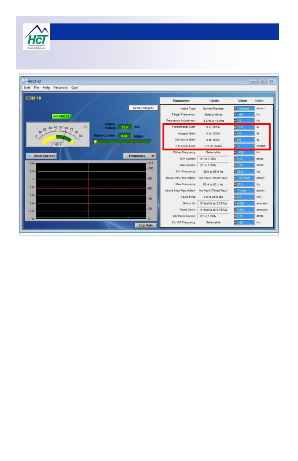
PID Tuning
Initial explanation of operation:
1.
See red outlined box above for location of setting described above:
2.
The PID loop time sets the number of cycle periods averaged between PID samples.
3.
The adjustment range is from 1 to 30 cycles - default setting is 8
4.
‘Cycle Period’ is the reciprocal of the frequency x 2 ( internal multiplication for accuracy )
which is 120 for a generator O/P frequency of 60Hz
5.
Corrective action sample rate at 60Hz is determined by: 1/(1/120 * 8) = 15Hz
6.
This means we sample the O/P frequency 15 times/Sec and correct speed as needed.
7.
A larger number of cycles, i.e. >8 will slow the controller response rate but will average out
any noise better because more samples are being used in the calculation.
8.
A smaller number of cycles i.e. <8 PID loop time cycle will increase the controller response
rate but could also be more susceptible to instability due to larger changes caused when a
noisy or unexpected cycle is included in the calculation.
9.
Changing the loop time will change the system’s response to the PID settings.
10. If the loop time is changed during ‘fine-tuning’, the PID setting sequence should be
repeated.
Oscillation:
In this instance the term ‘Oscillation’ describes the output frequency of the generator as it
‘wanders’ or ‘hunts’ around the ‘Target Frequency’ and means that it is not
‘locked-on-target-frequency’ and stable. This issue can be clearly heard, and is typically
caused by the pump being stroked and de-stroked. The output frequency can be viewed
on the PC Graphical user interface in the graphing section.