Ordering information, Typical applications – AMETEK 5400 Plug In Style Solid State Relay User Manual
Page 2
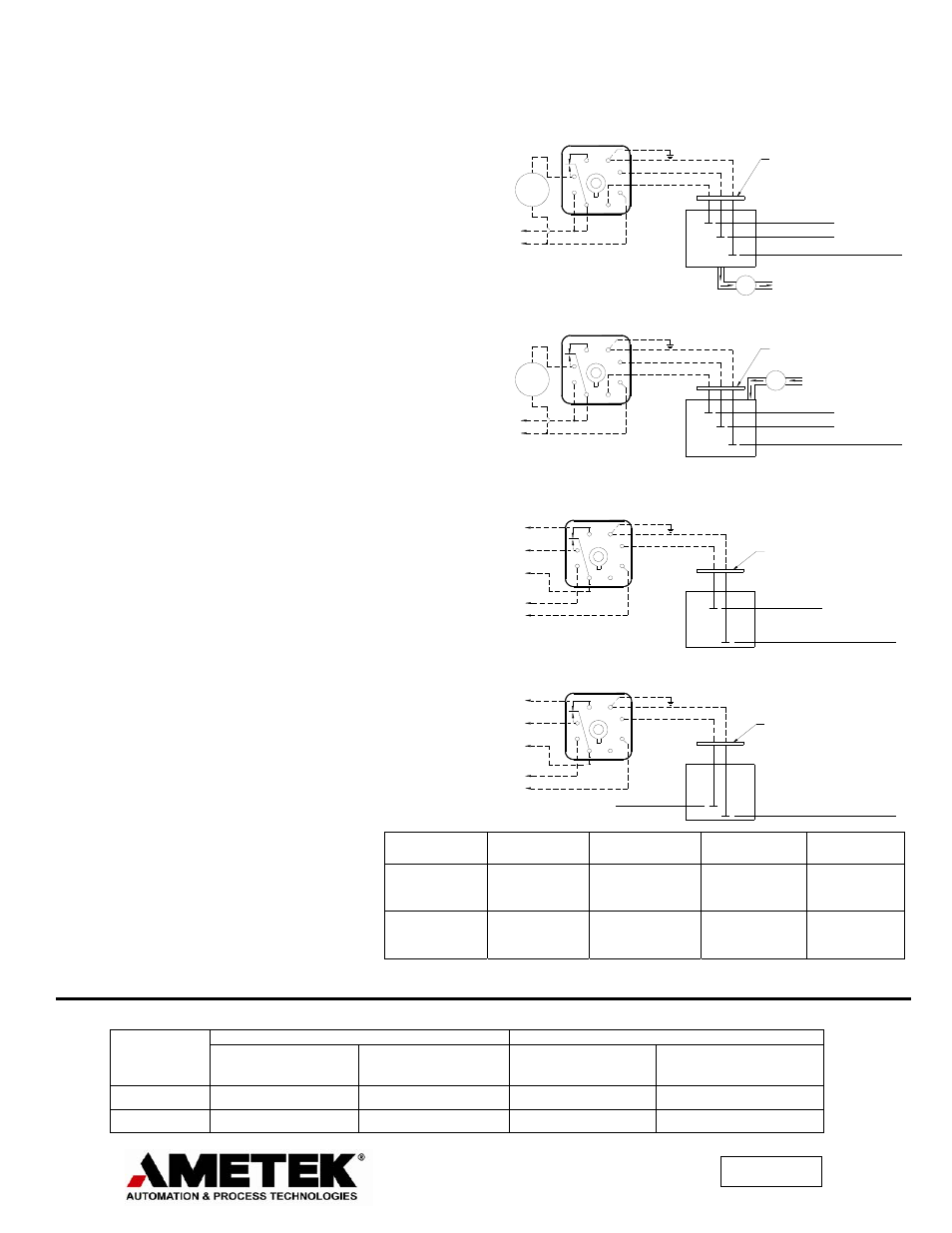
TYPICAL APPLICATIONS
Diagrams at right illustrate basic details of typical
application in which Series 5400 Relays are used as
original equipment components to provide fail-safe
control by de-energizing the load in event of power
of relay failure.
In Diagram 1, Type 5400-C Relay is used in direct
operation to provide automatic pump down control
for dehumidifiers, sumps or any other product
requiring control of a liquid at a given high-level set
point.
In Diagram 2, Type 5400-D Relay is used in inverse
operation to provide pump-up control for
carbonators, humidifiers, purification stills, etc.
where liquid must be kept above a low level set
point.
In Diagram 3, Type 5400-A Relay is used in direct
operation to provide high-level alarm.
In Diagram 4, Type 5400-B Relay is used in inverse
operation to provide low-level alarm.
ACCESSORIES
The 5400 relays require a standard 8 pin octal base
for mounting. In addition a hold down strap is also
available to secure the 5400 the relay to the octal
base in vibration environments.
INSTALLATION NOTES
Because Series 5400 Relays feature a low voltage,
low current sensing circuit, inexpensive small
gauge lead wires may be used between relays and
electrodes, sensors, or pilot switching devices.
Shielded cable is not required, and lead wires do
not have to be isolated from other wiring. Also, in
many level control applications, a common
electrode is not required so long as a good,
dependable metallic ground return from the relay to
the liquid is provided. The length of the control
wires, between the electrodes and the Series 5400,
are dependent on two factors, the control wire
configuration and the sensitivity setting, see
reference chart to the right.
Ordering Information
SINGLE LEVEL
DUAL LEVEL
Direct Operation
(High Level Alarm)
Inverse Operation
(Low Level Alarm)
Direct Operation
(Pump Down)
Inverse Operation
(Pump Up)
110 Volts A.C.
5400-A-L1 5400-B-L1 5400-C-L1 5400-D-L1
220 Volts A.C.
5400-A-L2 5400-B-L2 5400-C-L2 5400-D-L2
Telephone
Pair
Two #14
in open air
Two #14
in ½” conduit
Two #14
in lead sheath
Minimum
(1.0K ohms
Sensitivity)
In excess of
50,000 feet
In excess of
50,000 feet
In excess of
50,000 feet
8,000 feet
Maximum
(250k ohms
Sensitivity)
700 feet
530 feet
265 feet
35 feet
1080 North Crooks Road
• Clawson, MI 48017 USA
800-635-0289
• 248-435-0700 • Fax 248-435-8120
www.ametekapt.com
5400.B2R
11/02
• Z118
1
4
6
7
LOAD
5
8
HIGH PROBE
LOW PROBE
COM
LINE
VOLTAGE
START DRAIN
STOP DRAIN
GROUND RETURN TO TANK
OR COMMON ELECTRODE
SOLENOID VALVE
OR PUMP
B/W TYPE
5400-C RELAY
PUMP DOWN CONTROL
5400-C DIRECT OPERATION
DIAGRAM 1:
ELECTRODE
2
3
ELECTRODE
COM
LOW PROBE
HIGH PROBE
DIAGRAM 2:
5400-D INVERSE OPERATION
PUMP UP CONTROL
LOAD
VOLTAGE
LINE
5
4
1
3
2
8
7
6
5400-D RELAY
B/W TYPE
OR COMMON ELECTRODE
GROUND RETURN TO TANK
OR PUMP
SOLENOID VALVE
STOP FILL
START FILL
{
{
HOLDER
HOLDER
HOLDER
ELECTRODE
COM
PROBE
DIAGRAM 3:
5400-A DIRECT OPERATION
HIGH LEVEL ALARM
VOLTAGE
LINE
5
4
1
3
2
8
7
6
5400-A RELAY
B/W TYPE
OR COMMON ELECTRODE
GROUND RETURN TO TANK
HIGH LEVEL
{
N.O.
COM.
N.C.
COM
PROBE
DIAGRAM 4:
LOW LEVEL ALARM
5400-B INVERSE OPERATION
LINE
VOLTAGE
{
N.C.
N.O.
COM.
B/W TYPE
5400-B RELAY
3
2
1
4
6
8
7
5
OR COMMON ELECTRODE
GROUND RETURN TO TANK
LOW LEVEL
ELECTRODE
HOLDER
ELECTRODE
HOLDER