AMETEK 5200 Solid State Relay User Manual
Page 4
Copyright 2007 by AMETEK Automation & Process Technologies
1080 N. Crooks Road, Clawson, MI 48017 Toll Free 800-635-0289
Phone 248-435-0700 Fax 248-435-8120 www.ametekapt.com
432
5200.M4R
5/07.Z152
G - One Level Operation
If load relay operates at one level only (starts and stops at one electrode), check
following:
1. Electrode Wires - See Section B-1.
2. Holding Circuit
If the holding circuit (contacts 1-7) is not opening, the load relay will operate from
the lower electrode only. If holding circuit is not closing, the relay will operate from
the upper electrode only. As in Section B-2 for direct operation, if contact 1-7 is
defective, contacts 2-8 can be used as an alternate holding circuit contact.
H - Intermittent Operation
If load relay occasionally short cycles or operates intermittently, check the
following:
1. See Section C-1 and C-2.
2. Check Section J-3 and J-5.
I - Constant Chatter
If load relay chatters continuously, check as in Section F-2. If relay now operates
correctly, check Sections J-3 & J-5, G, and H.
If load relay still chatters with terminals 14 & 15 disconnected, the relay is
defective or there is a defective capacitor in the circuit board.
J - Load Relay Will Not Drop Out
If the relay will not drop out when the liquid touches upper electrode, check the
following:
1. Defective Control - See F-2.
2. Poor Ground Connections
A good dependable ground connection should be made to terminal 15 to complete
the circuit back to terminal 14 as indicated in Section A-3.
3. Broken Wires
A broken or loose wire from the control to upper electrode or ground (common
electrode) will prevent load relay from dropping out. Check as in Section A-4, but
“pull in” should be replaced with “drop out” in the description.
4. Sensitivity Resistor Too Low
If the sensitivity is too low, the load relay will not drop out, or will buzz and chatter.
See A-5, but “pull in” should be replaced by “drop out”.
5. Fouled Electrodes
Accumulated deposits on the electrodes will insulate them, and prevent
the load relay from dropping out. See Section A-6.
6. Electrodes Too Short - See Section A-7.
CONTROL REPAIRS
All B/W controls are tested at the factory prior to shipment to insure proper
operation. They should be handled with care during installation to avoid breaking
electrical connections. If the control does not operate properly after it has been
installed, and service instructions indicate a defect, repair should be attempted
only by an experienced electronic technician as follows:
CHECK TRANSFORMER
With the ac line voltage applied to terminals 10 & 11 or 10 & 12 as shown on
Form 448, the following voltages should be read between the transformer wire
connections on back of the control (±15%):
Black to Orange ..........................115 volts
Black to Blue .............................. 230 volts
Red to White ............................... 3.6 volts
Red to Brown .............................. 7.2 volts
Brown to White ........................... 3.6 volts
Green to Yellow ........................... 30 volts
If these out-put voltages are not present, and in-put voltages check, the
transformer is defective and should be replaced.
TEST CIRCUIT BOARD AND LOAD RELAY
Direct Operation
Test the control as in A-2 with jumper between terminals 13 & 14. If load relay
does not pull in, check on circuit board between two black wires leading from
load relay for a reading of 22 to 26 volts dc. If the voltage reading is low, the
circuit board is defective. If the voltage reading is high (39 to 44 volts dc), the
load relay has an open coil.
Inverse Operation
Test the control as in F-2 with jumper removed. If load relay does not pull
in, check as above for 22 to 26 volts dc. If voltage is low, circuit board is
defective. If voltage is high (39 to 44 volts dc), load relay has an open coil.
Replace the circuit board or the load relay as required. See parts list for
details. If a competent technician is not available, the control should be
returned to factory for repair or replacement.
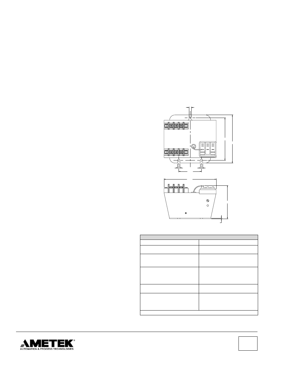
5200 RELAY CHASSIS DIMENSIONS
Replacement Parts for 5200 Solid State Controls
Description
Part Number
Resistor Set - Low
Resistor Set - High
52-110105
52-120105
*Potentiometer Kits for 5200-LV
Range LV1
Range LV2
52-110205
52-110206
*Potentiometer Kits for 5200-HV
Range HV3
Range HV4
Range HV5
52-120205
52-120206
52-120207
Circuit Board - Low
Circuit Board - High
52-110114
52-120114
Transformer
Load Relay
Terminal Block - Line
Terminal Block - Probe
52-110106
04-261900
04-281900
04-281800
*See Sensitivity Range table shown on page 2.