7250x digital stik stainless steel sensor – AMETEK 7250 Digital Stick User Manual
Page 2
AUTOMATION & PROCESS TECHNOLOGIES
®
Accessories
Item
Part Number
Float Kit, 316 SS, 2.05” Diameter w/ E Clip and Spacer 0.54s.g.
SD0515000
Float Kit, Nitrophyl, 2.02” Diameter w/ E Clip and Spacer 0.40s.g.
SD0536500
Cable Assembly, 4 pin, 6 feet long (M style only)
01533141
Adjustable Tube Coupling 5/8” x 3/4” NPT
04283800
Junction Box, side mount, N4X with zero & span push buttons
SD0536101
Bushing, 3/4” x 2” NPT 316SS
04587241
Wiring Diagram
Part Numbering
7250X Digital Stik Stainless Steel Sensor
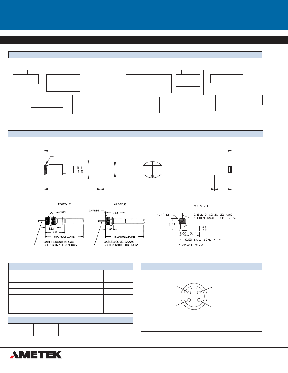
Dimension Drawing
1080 N. Crooks Road, Clawson, MI 48017-1097
Phone: 248.435.0700 Toll Free: 800.635.0289 Fax: 248.435.8120 www.ametekapt.com
Copyright 2011 by AMETEK Automation & Process Technologies. All Rights Reserved.
7250X.D5
.Z193
725
0
X
M
LLL
F1
XXX
X
XX
Overall Length
In 1” increments
i.e. 072 = 72”
(Min 18” Max 288”)
Mounting Style
X = None
Connector Style
M = 4 Pin Mini
R = 1/2” NPT Right Angle
D = 3/4” NPT Dual
S = 3/4” NPT Single
7250
Digital Stik
Output Protocol
2 = 25 level readings
5 = 10 level readings
Span
In 1” increments
i.e. 072 = 72” (Min 8” Max 278”. Max
span is equal to overall length -10)
# of Floats
F1 = 1 Float
F2 = 2 Floats
Special Mounting
XX = None
Style/Material
X = 316 Stainless Steel
Consult factory for other
options.
7/8-16 UNS-2A
1.00
8.00" NULL ZONE
OVERALL LENGTH (O.A.L.)
TEMPERATURE SPAN
.625
2.00"
DEAD
BAND
M STYLE
M Connector
Drain
(Cable Shield, chassis
gorund on ss housing
probes)
Common
(Black wire)
Data Signal
(White wire)
Power
(Red wire)
Connector View
Contact Factory for additional drawings.
1
2
4
3
RX
Number of Temp Points
R1 = 1 Sensor,18”*
R5 = 5 Sensors
T1 = 1 Sensor, 4”*
*From the bottom of the probe.
Intrinsically Safe Entity Parameters
V
max
I
max
P
I
C
I
L
I
7.93 V
280mA
1.0 W
30.1μF
0μH
7250X.D5R
05/12.Z193