Mounting of unit, Establishing camshaft direction of rotation, Cam settings – AMETEK 1980 Rotating Cam Limit Switch User Manual
Page 3: Easy set-up procedure
3
Mounting of Unit
Mount the assembly and couple input shaft to the
driving member with the shaft keyway up and in line
with the positioning arrow on the bearing end plate.
The machine should be in the start cycle position.
Establishing Camshaft
Direction of Rotation
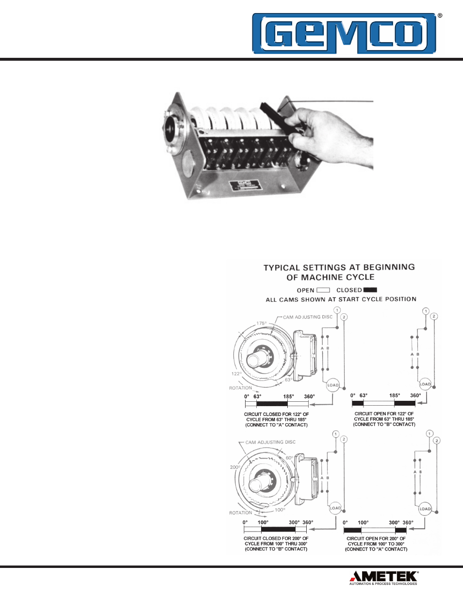
Cam settings should be made with the
Camshaft uppermost to the viewer. The picture
at the top right illustrates this viewing position
and also shows the adjusting tool being applied
to the adjusting wheel. Shaft rotation is always
established off the right end of the unit even
when the input shaft, whether direct or through
a gear reducer, is situated at the left end. As an
aid to designating shaft rotation when a gear
reducer is used, consult page 14 of this catalog
section.
Cam Settings
For clockwise rotation, set ‘’make’’ angle with
the black dial and ‘’break’’ with the red dial for
dwell settings less than 180°. Reverse colors for
dwells 180° or greater.
For counterclockwise rotation, set ‘’make’’ angle
with the white dial and ‘’break’’ with the yellow
dial. Reverse colors for dwells 180° or greater.
Switch connections should be made in
accordance with the illustrations to the right,
which incidentally are both clockwise rotating
examples.
Easy Set-Up
Procedure
READ CAM
SETTING HERE
SWITCH SIDE
One Turn of Adjusting Dial
Moves Cam 10°
(Adjusting Tool #P0034600
Inside Cover of Each Unit)
ALWAYS VIEW
CAMSHAFT ROTATION
FROM RIGHT SIDE
FRONT SIDE
1080 N. Crooks Road • Clawson, MI 48017-1097 USA • 800.635.0289 • 248.435.0700 • Fax: 248.435.8120 • www.AMETEKAPT.com