Specifications, Accessories, Part numbering – AMETEK 955A Brik LDT User Manual
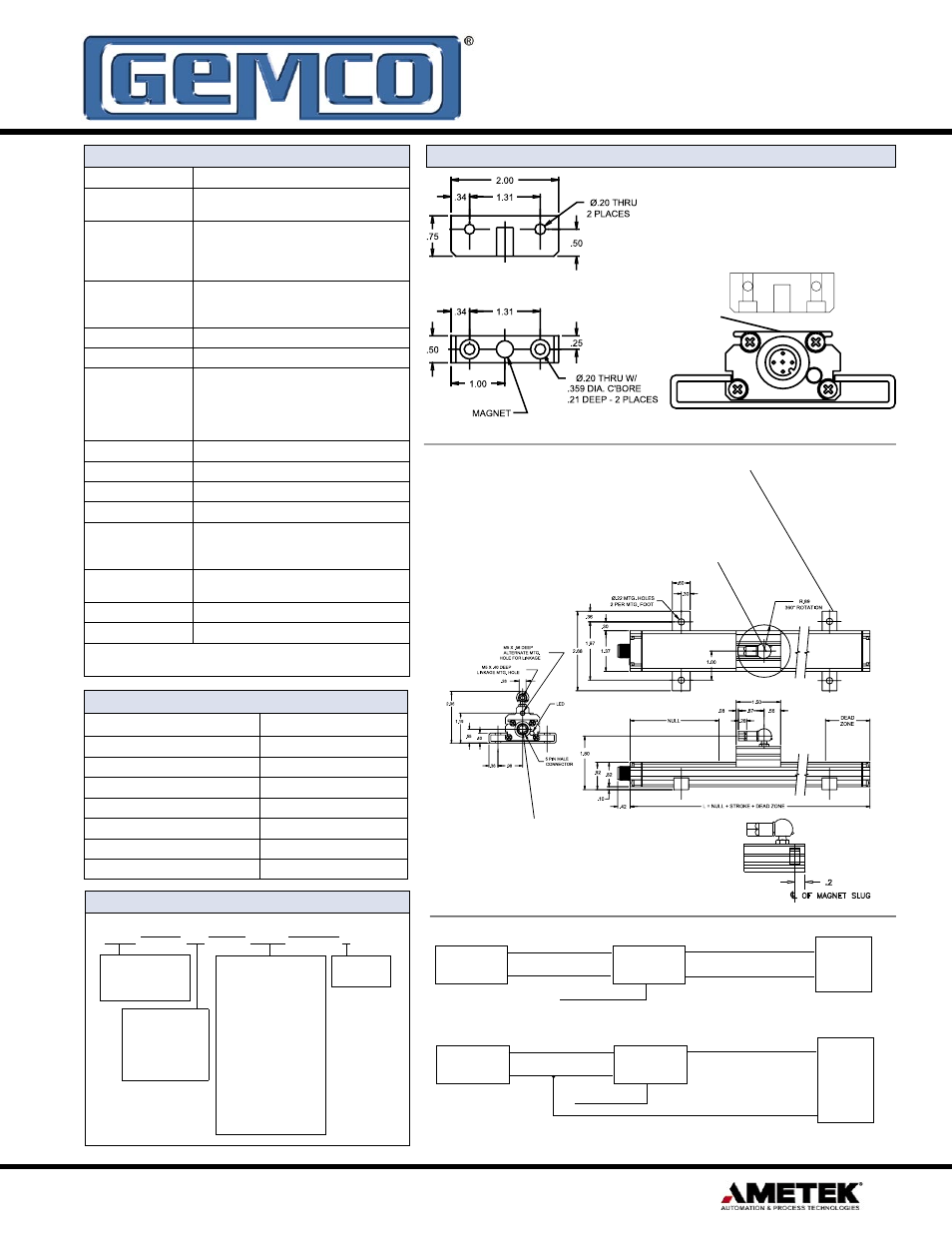
Page 3: Dimensions
3
1080 N. Crooks Road • Clawson, MI 48017 • 800.635.0289 • 248.435.0700 • Fax 248.435.8120 • www.AMETEKAPT.com
Note: 955A-C is current sourcing, which allows the current to flow from the LDT into
the user’s equipment.
Differential Input
Power
+
Supply
_
955A
LDT
+ Input
- Input
Customer Supplied Power (Brown)
Power Supply Common (Blue)
Position Output (Black)
Position Common (Gray)
Program Input (White)
Single Ended Input
Power
+
Supply
_
955A
LDT
+ Input
Common
Customer Supplied Power (Brown)
Power Supply Common
Position Output (Black)
Program Input
(White)
(Blue)
Specifications
Input Voltage
13.5 to 30 VDC
Current Draw
2.5 Watts Maximum,
120 mA @ 15 VDC Typical
Output
0 to 10 VDC
10 to 0 VDC
4 to 20 mA
20 to 4 mA
Resolution
Internal
Analog Output
0.001”
16 Bit (1 part in 65,535)
Non-Linearity
+/- 0.05% of Stroke
Repeatbility
+/- 0.006% of Full Stroke
Update
40” or less
41” to 100”
101” to 150”
151” to 180”
1mS (Stroke Lengths 40” - 50”)
2mS (Stroke Lengths 41” - 100”)
3mS (Stroke Legnths 101” - 150”)
4mS (Stroke Lengths 151” - 180”)
Operating Temperature
-20° to 70° C
Span Length
5” to 180”
Null Zone
3.00”
Dead Zone
2.00”
LED
Green = Power is applied and magnet is present.
Red = Fault, magnet is in the Dead Zone or lost
Yellow = Out of the active programmed range
Connector
Standard 5 Pin Micro
12mm Euro Connector
Approvals
CE
Enclosure
IP67, Optional IP68
Specifications are subject to change without notice.
Specifications are based on a typical 36” LDT.
Accessories
Item
Part Number
Slide Magnet
SD0521800
Float Magnet
SD0522100
Mounting Foot
SD0522000
6 Ft. Cable
949019L6
12 Ft. Cable
949019L12
6 Ft. Cable; Right Angle Connector
949020L6
12 Ft. Cable; Right Angle Connector
949020L12
Part Numbering
955A
XX
XXXX
X
Stroke Length
Insert stroke in inches
to 0.1 inch. Enter as
a four-place number.
Valid lengths are 0050
to 1800. Example:
12.0 inch probe stroke
is entered as 0120. To
convert a metric stroke
in millimeters, multiply
millimeter value by
0.03937 to arrive at inch
value.
955A BRIK
with Analog
Output
Output
V0 = 0 to 10 VDC
V1 = 10 to 0 VDC
C4 = 4 to 20mA
C2 = 20 to 4mA
Options
X = None
Dimensions
Mounting brackets (SD0522000) slide in the grooves on the side of the
extruded housing. When tightened down with fastening hardware the
mounting brackets clamp the unit into place. It is recommended to use
one mounting bracket on each end and every three feet between.
A standard female swivel mounting arm is provided with the slide magnet
assembly. For extensions and other options contact the factory.
A standard 12 mm 5 pin micro connector is used. Straight mating
cables can be ordered in a 6’ length (949019L6), or 12’ length
(949019L12). If space is a consideration a right angle connector is
also available, (949020L6 or 949020L12).
* WARNING: do not use cord sets with LED’s
N
S
Floating Magnet Assembly (SD0522100)
Sensing Surface
NOTE: The north pole of the magnet should be pointed towards the probe.