Spring removal: a2, Spring installation: a1, Spring installation: a2 – AMETEK 925 Linear Cable Reel Sensor User Manual
Page 2
SERIES 925 (A1 & A2)
INSTALLATION & SERVICE BULLETIN
1080 N. Crooks Road, Clawson, MI 48017-1097
Phone (248) 435-0700 FAX (248) 435-8120
For Sales & Technical Assistance Call 800-635-0289
A Product of
FORM1054
Rev. B
5/1/03
SPRING REMOVAL: A2
The input from the drum shaft to the spring
package is similar to the A1 model, but
everything else is unique. Both spring tangs
are connected to the spring transfer
assembly (see Fig. 5).
CAUTION: The two spring tangs are reverse-
mounted to each other. It is important that the
direction of engagement on the steel lug is
noted when the springs are removed and
duplicated when reinstalled.
SPRING INSTALLATION: A1
1) Inspect the spring housing to see if a clear
plastic spacer is inside. If not, place it in now
before installing the spring.
2) Slide the “C” clamp (around the O.D. of the
spring) close to one edge of the spring. Drop
spring into the spring housing, ensuring that
the outer spring tang is aligned with the slot
on the housing, and the “C” clamp is facing
out.
3) Slip the blade of a small screwdriver under
the spring tang and guide the tang into the
housing slot. Grasp the spring by the “C”
clamp and push it into the housing with your
thumbs, removing the “C” clamp at the same
time. (CAUTION: The “C” clamp must not be
removed before placing the spring in housing.
The spring will unwind, causing bodily harm
and rendering the spring useless).
4) Seat the spring tang in the housing slot
securely, while removing the screwdriver.
5) Place the remaining plastic spacer over
the spring. While holding the spacer in the
housing, mount spring assembly to the 925
unit by sliding inner spring tang into slot on
5/16” rollpin. Hold the spring assembly in
place while re-attaching servo clamps. Do
not tighten clamps at this time.
6) Refer to step 3 under SPRING TENSION
ADJUSTMENT for adjusting spring tension.
SPRING INSTALLATION: A2
1) Refer to steps 1 and 2 of SPRING
INSTALLATION: A1, except when placing
the first spring into the spring housing, ensure
that the inner spring tang slides into the
rollpin mounted inside the spring housing.
2) Place spring transfer assembly over first
spring, seating the outer spring tang over the
horizontal steel bar on the transfer assembly.
Place another plastic spacer over the spring
transfer assembly.
3) Refer to step 2 of SPRING
INSTALLATION: A1 when installing the
second spring. When placing the spring into
the housing, ensure that the outer spring tang
is seated on the opposite side of the transfer
assembly bar as that of the first spring.
4) To complete spring installation, refer to
step 5 of SPRING INSTALLATION : A1.
5) Refer to step 3 under SPRING TENSION
ADJUSTMENT for adjusting spring tension.
For ordering information of replacement parts
for the 925 A1 or A2 unit, please refer to the
OPTIONAL SPARE PARTS segment of
SECTION 925 in the Gemco catalog.
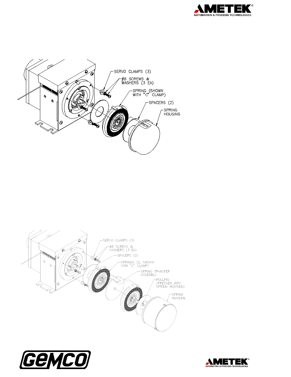
Fig. 4 Spring assembly parts - 925 A1
Fig. 5 Spring assembly parts - 925 A2