2 terminal assignments, 3 connection conditions, 6 connection in control cabinet – ARI Armaturen RI21 EN User Manual
Page 9
Rev. 0040602000 1014
Page 2-9
Operating and installation instructions
Electronic position indicator RI21
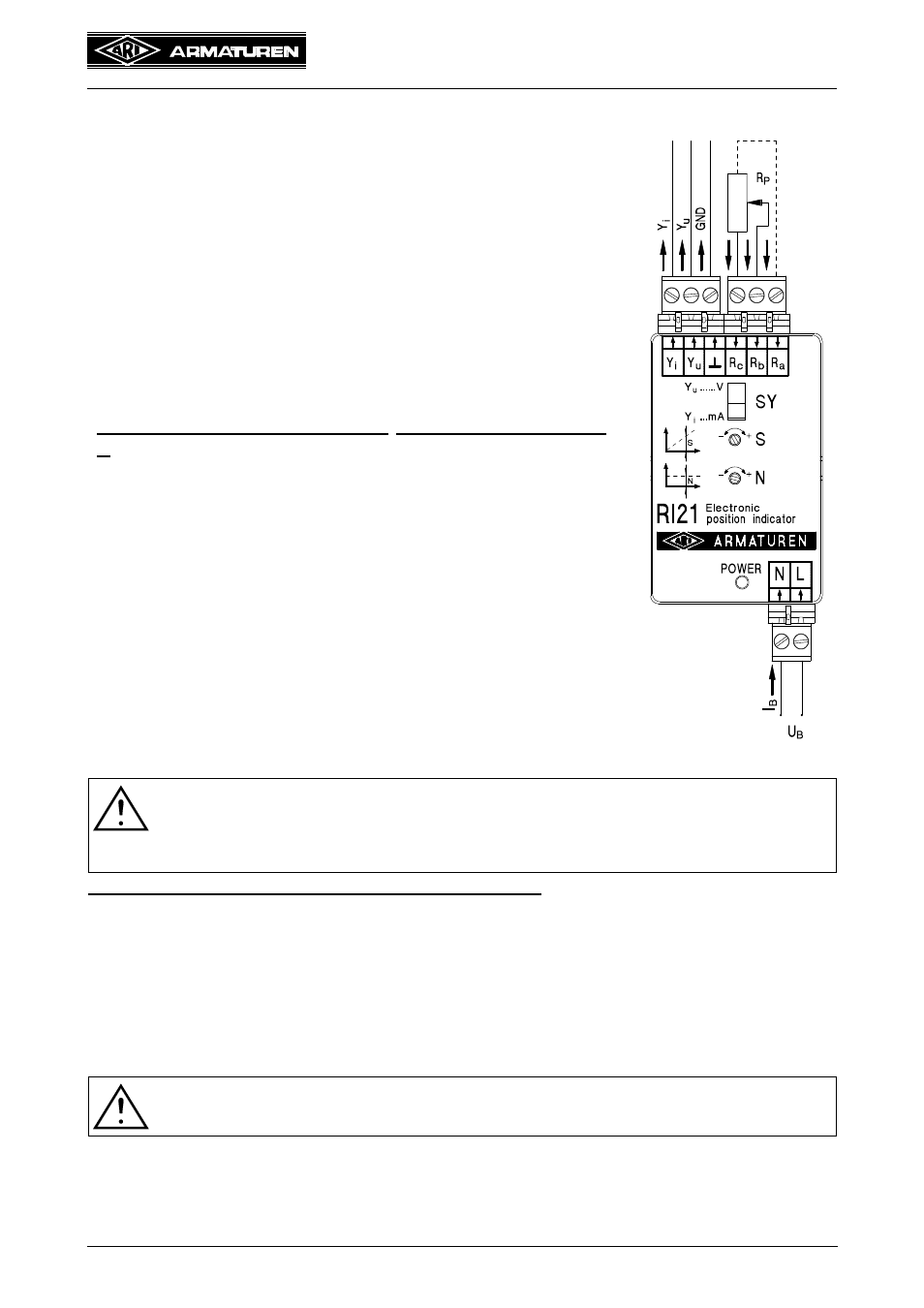
5.5.2 Terminal assignments
Power input
N
Terminal - power input
Neutral conductor
L
Terminal - power input
Phase
Actuating signal output
Y
i
Terminal - output signal
+...20 mA DC
Y
u
Terminal - output signal
+...10 V DC
Terminal - ground, GND.................0 V
Potentiometer input
R
P
Potentiometer ...............................0...1000
R
a
Terminal - potentiometer input
dashed line (yellow wire)
must‘nt be connected because R
a
is internally wired with
R
b
R
b
Terminal - potentiometer input ......(grey wire)
R
c
Terminal - potentiometer input
(red wire)
Fig. 5
5.5.3 Connection Conditions
All electrical terminals are connected to the electronic position
indicator RI21 by means of series isolating terminals. The
suitable conductor cross-sections for connecting the terminals
are 0.2 to 2.5 mm
2
. To achieve optimal electromagnetic
compatibility it is recommended to use shielded cables for
connecting potentiometers or standardized active current or
voltage signals.
Please contact the manufacturer direct for technical
information.
ATTENTION !
To facilitate use in 3-conductor technology, the ground output
may be
connected to the N contact of the power input only in the 24 V AC version.
The new contact is then referred to as zero potential (0V)
Fuse protection of mains power supply on system side: 6 A max.
5.6 Connection in Control Cabinet
Power input for connection in control cabinet
The voltage supply is connected to terminals N and L in accordance with the type
identification plate.
Actuating signal output for connection in control cabinet
The actuating signal output ...20 mA is connected to terminals Y
i
and
.
The actuating signal output ...10 V is connected to terminals Y
u
and
.
ATTENTION !
Only one actuating signal output may be connected at any one time.
Potentiometer input for connection in control cabinet
A 1000 Ohm potentiometer is connected to terminals R
a
, R
b
, R
c
.
The wiper is connected to R
b
.
With the valve closed, there are 0 Ohms between R
b
and R
c
.
............
...................
............
...................
............
.................
...........
.................
............
..........
...........
...............
..........
...........
.......