0 troubleshooting, 0 troubleshooting table – ARI Armaturen RI21 EN User Manual
Page 21
Rev. 0040602000 1014
Page 2-21
Operating and installation instructions
Electronic position indicator RI21
8.0 Troubleshooting
In the event of malfunction or faulty operating performance check that the installation and
adjustment work has been carried out and completed in accordance with these Operating
Instructions.
-
ATTENTION !
It is essential that the safety regulations are observed when identifying faults.
If malfunctions cannot be eliminate with the help of the following table
“9.0 troubleshooting table”, the supplier or manufacturer should be consulted.
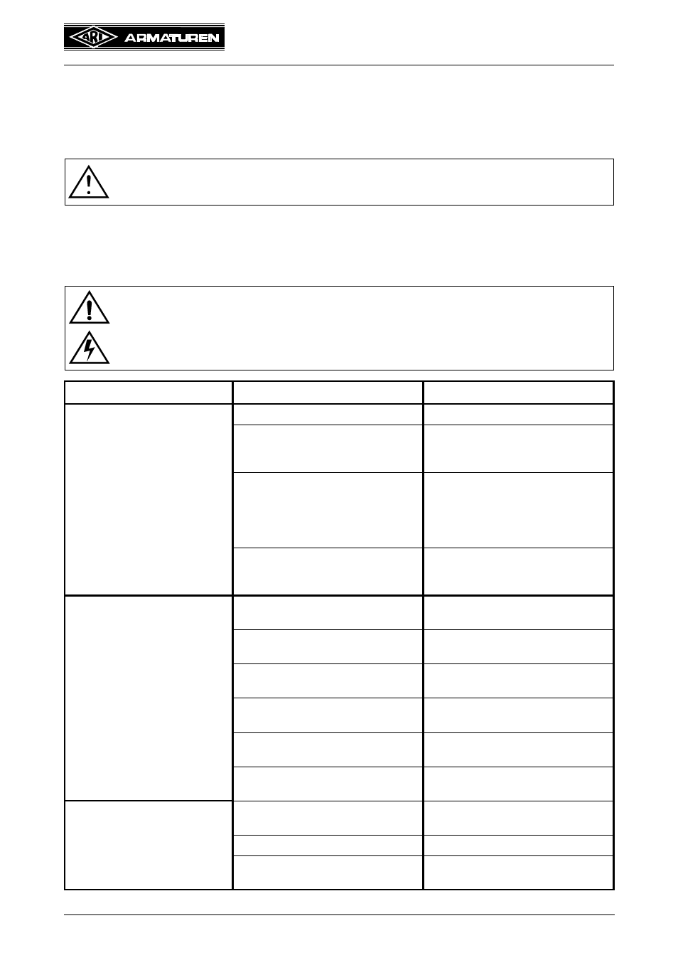
9.0 Troubleshooting table
ATTENTION !
- read point 10.0 and 11.0 prior to dismantling and repair work!
- read point 6.0 before restarting the plant !
Faults
Possible causes
Corrective measures
Yellow LED is not lit
- Mains failure
- Check power supply
- Incorrect operating voltage
- Connect operating voltage in
accordance with type identification
plate
- electronic position indicator burnt
out
- Check whether mains voltage
agrees with the voltage specified
on type identification plate.
Replace electronic position indica-
tor.
- Connection terminal not connected
correctly or cable has no contact in
connection terminal
- Firmly plug in connection terminal
and check connection cable
electronic position indicator can-
not be adjusted
- Potentiometer not connected cor-
rectly
- Check connections
- Potentiometer has incorrect value
rating
- Replace potentiometer by
1000
potentiometer
- Potentiometer connected to incor-
rect terminal
- Correct connection in accordance
with circuit diagram
- No signal present at output
- Perform settings as under 6.0
through 6.5
- Actuating signal connected to incor-
rect terminal
- Correct connection in accordance
with circuit diagram
- Adjusting screws N (zero point) and
S (slope) are out of range
- Carry out settings as described
Output positioning signal in-
capable of being set over the
entire setting distance
- Spur gear transmission ratio at
potentiometer incorrect
- Adapt spur gear transmission ratio
to control range
- Wrong potentiometer
- Use 1000 ohm potentiometer
- Adjusting screws N (zero point) and
S (slope) are out of range
- Carry out settings as described