ARI Armaturen drainer PN40 EN User Manual
Page 6
Page 6
Rev. 0040807000 2404
Operating and installation instructions
Liquid drainer
5.2 Installation instructions for welding
(refer to Fig. 1 page 4)
Please note that only qualified persons using appropriate equipment and working in
accordance with technical rules are allowed to install fittings by welding.
The responsibility for this lies with the system owner.
Please refer to the catalogue sheet for information on type and instructions relating to
welding socket weld ends/butt weld ends.
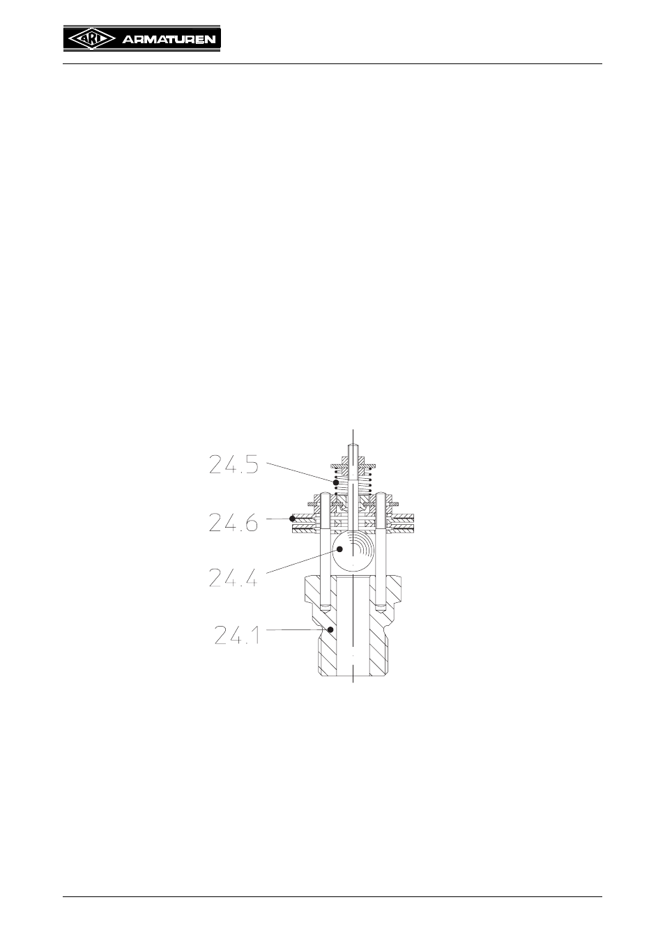
When welding products to the pipeline system these should be adequately cooled to
prevent any adverse effect on the complete controller assembly (Pos. 24) and possibly the
flat gasket (Pos. 17). The heat-affected zone should be restricted to the immediate weld
seam area!
Note pre- and post-welding heat treatment in accordance with Material Fact Sheet
DIN EN 10222.
If there are plans to etch the facility before putting it into operation, the complete controller
assemblies (Pos. 24) should be removed, replaced by etch inserts, and refitted after
etching (see 7.1). In such an event please contact the manufacturer.
5.3 Controller adjustment
The factory setting guarantees closure of the liquid drainer at a differential pressure of
ΔP = 1.5 bar.
5.4 Steam trap testing through ultrasonic measurement
Testing the operation of the steam trap in the installed state is straightforward with the
“ARImetec
®
-S” multifunction tester.
Refer to data sheet „ARImetec
®
-S “.
Fig. 3: Bimetallic controller