1 factory setting, 2 special setting, 3 version with plug in screw cap (series 602/603) – ARI Armaturen CONA B PN630 EN User Manual
Page 9: Operating and installation instructions cona, B - bimetallic steam trap
Rev. 0040803000 4610
Page 9
Operating and installation instructions
CONA
®
B - Bimetallic steam trap
5.3.1 Factory setting
(see Fig. 11 - Fig. 12 page 8)
The bimetallic controller is set at the factory, but may be adjusted for special operating
conditions if required. Should the controller be inadvertently misadjusted by the operator,
the factory setting can be roughly reset as follows:
- Let bimetallic controller cool to room temperature (20-25°C)
- Slacken hexagon nut (pos. 24.8)
- Rotate spindle (pos. 24.3) to the left with a screwdriver until a slight resistance is felt. The
valve ball (pos. 24.4) now rests against seat (pos. 24.1) or seat bushing (pos. 24.9).
- Rotate spindle (pos. 24.3) back to the right as shown in the table:
- Tighten hexagon nut (pos. 24.8), holding against bimetallic assembly (see 7.3).
5.3.2 Special setting
(see Fig. 11 - Fig. 12 page 8)
If increased sub-cooling is required for the heating process, the spindle (pos. 24.3) must be
rotated to the left. If less condensate sub-cooling or maximum hot water output is required,
rotate spindle (pos. 24.3) to the right. A 1/4 turn is roughly equal to a temperature change of
10K.
Please note that settings should only be changed when the unit is cold. After correcting the
setting, properly retighten the hexagon nut (pos. 24.8) (see 7.3).
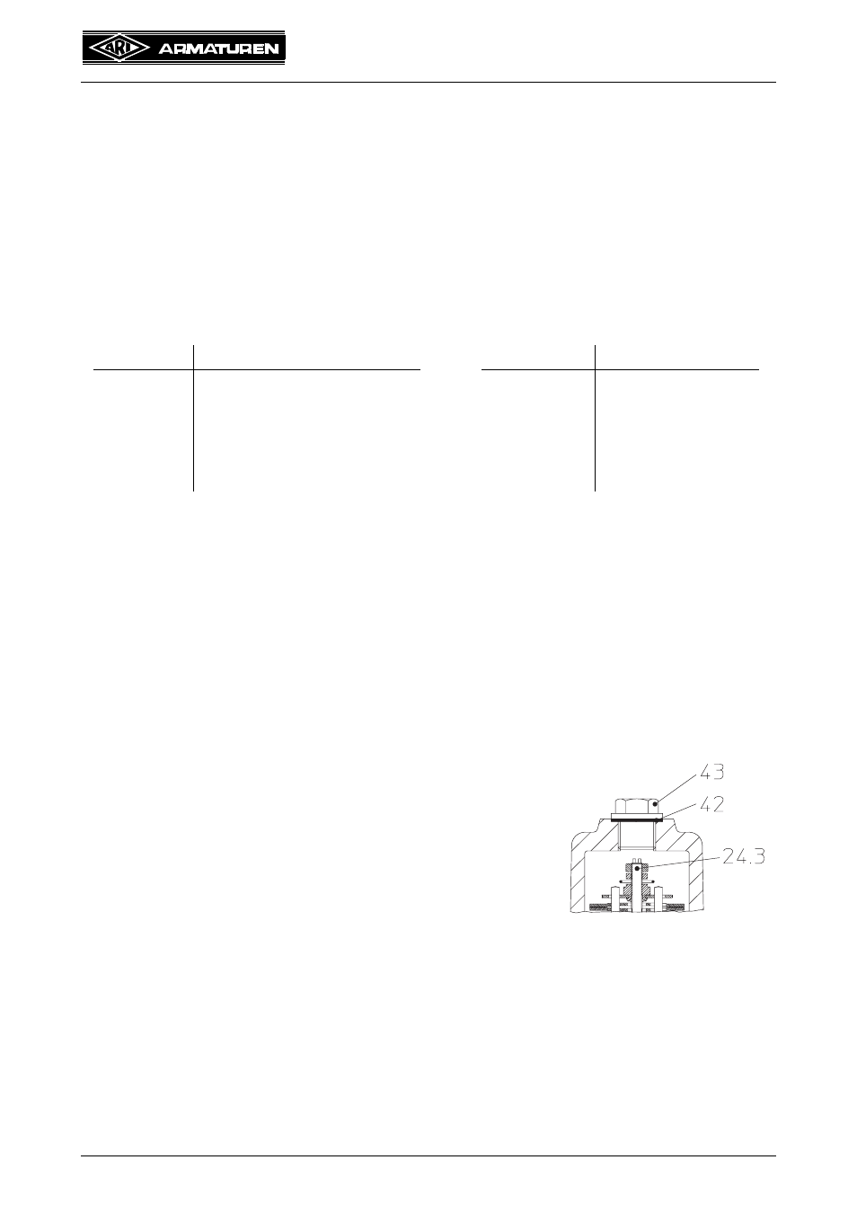
5.3.3 Version with plug in screw cap (series 602/603)
5.4 Steam trap testing through ultrasonic measurement
Testing the operation of the steam trap in the installed state is straightforward with the
“ARImetec
®
-S” mulitfunctional testing device.
Refer to data sheet “ARImetec
®
-S”.
controller
rotations
controller
rotations
DN15-25
DN32-50
DN15-25
R13
4,25
5,7
R60
4
R22
3,75
5,7
R90
2,6
R32
3,25
5,9
R130
3,6
R46
4
--
R150
3,7
R56
--
6
R270
3,2
In this version the controller setting can be changed without
dismantling the screw cap/cover.
To do this remove the plug (pos. 43) in the unpressurised
state and, using a screwdriver, adjust the spindle (pos. 24.3)
direct from outside. The same particulars apply as in items
5.3.1 and 5.3.2. After adjustment, tighten the plug (pos. 43)
(see 7.3).
Fig. 13