3 bellows seal design – ARI Armaturen STEVI 471 EN User Manual
Page 10
Page 10
Rev. 0040305000 0410
Operating and installation instructions
Straight through control valves - STEVI
®
470 / 471
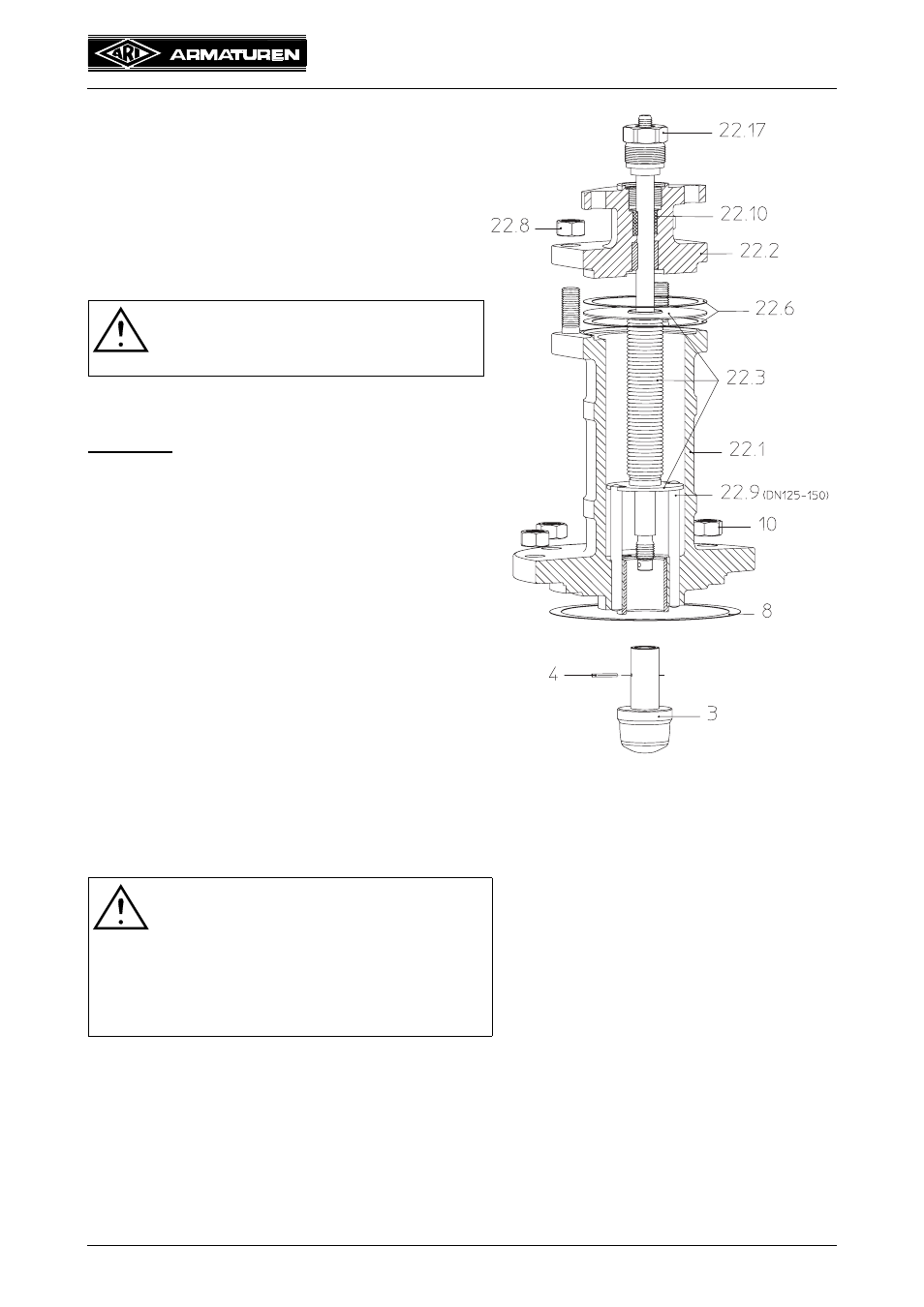
7.1.3 Bellows seal design
If the stem leaks the bellows seal (pos. 22.2) is
defective. The leak can initially be stopped by
tightening the screw joint (pos. 22.17)
respectively the sleeve nut (pos. 22.16).
Stem and bellows (pos. 20.3) can only be
replaced together.
Replacement of bellows seal:
- Remove actuator.
(Refer to operating instructions for actuator!)
DN15-150
- Loose nuts (pos. 10).
- Detach bellows assembly (pos. 22).
- Slacken screw joint (pos. 22.17) by about one
turn.
- Press stem-/bellows unit (pos. 22.3) down.
- Drive pin (pos. 4) out with a drift.
- Unscrew plug (pos. 3).
- Loose nuts (pos. 22.8).
- Detach mounting bonnet (pos. 22.2).
- Extract stem-/bellows unit (pos. 22.3) from
the bellows housing (pos. 22.1).
- Bolt new parts together and drill them.
- Replace 2 gaskets (pos. 22.6) and 1 gasket
(pos. 8).
- Assemble in reverse order.
- Secure with nuts (pos. 10 and 22.8) and tighten them crosswise.
(For tightening torques refer to item 7.3.1)
- Tighten screw joint (pos. 22.17) resp. sleeve nut (pos. 22.16) gradually up to tightness of
the stuffing box packing (pos. 22.10).
ATTENTION !
Refer to item 10.0 and 11.0 before
dismantling the valve.
ATTENTION at DN125-150!
- Ensure that the torsion lock is
correctly positioned when inserting
new stem/bellows unit. Introduce the
grooved pin (pos. 20.9) into the
torsion lock groove.
Make sure it runs smoothly!
Fig. 14: Series 471 DN 15-150