Sensor wiring, Figure 10 wiring of the sensors, Table 4 – Vaisala WAT12 User Manual
Page 20: I/o connectors
User's Guide ________________________________________________________
18 _____________________________________________________M210309EN-A
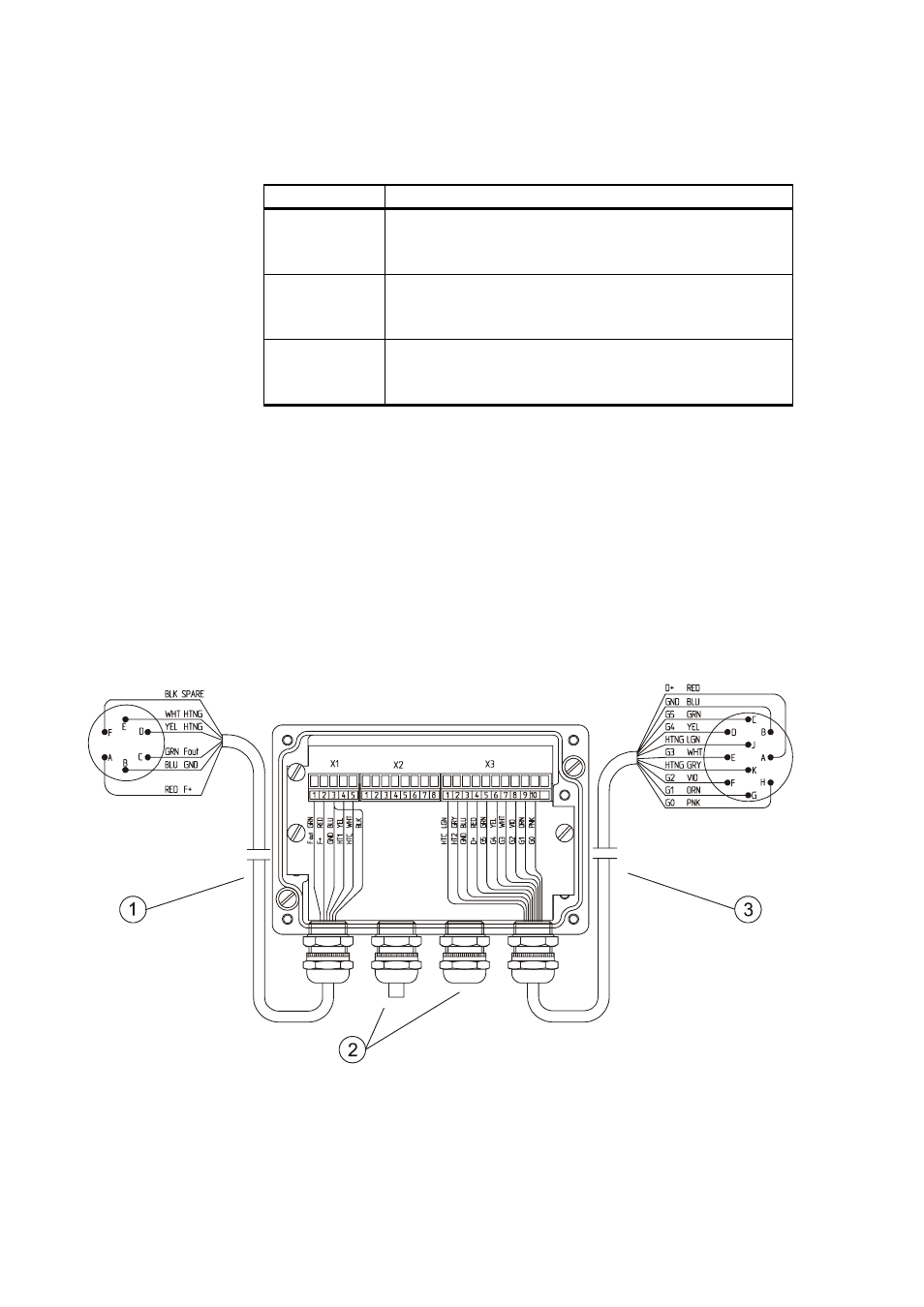
Table 4
I/O Connectors
Connector
Description
X1
Plug-in connector with screw terminals (5 pcs)
for the anemometer cable. Maximum wire cross
section area is 1.5 mm2.
X2
Plug-in connector with screw terminals (8 pcs)
for the power and signal cable. Maximum wire
cross section area is 1.5 mm2.
X3
Plug-in connector with screw terminals (11 pcs)
for the wind vane cable. Maximum wire cross
section area is 1.5 mm2.
Sensor Wiring
The transmitter connects to the wind sensors with the cross-
arm's standard cables through two cable glands. Through
these cables the WAT12 transmitter both feeds the sensor
power and receives the wind data. Plug-in type screw
terminal connectors are provided both for the sensor cables
and the output line cable.
0206-048
Figure 10 Wiring of the Sensors