Vaisala Real-time Display Software YOURVIEW User Manual
Page 22
User's Guide ______________________________________________________________________
20 __________________________________________________________________ M210681EN-B
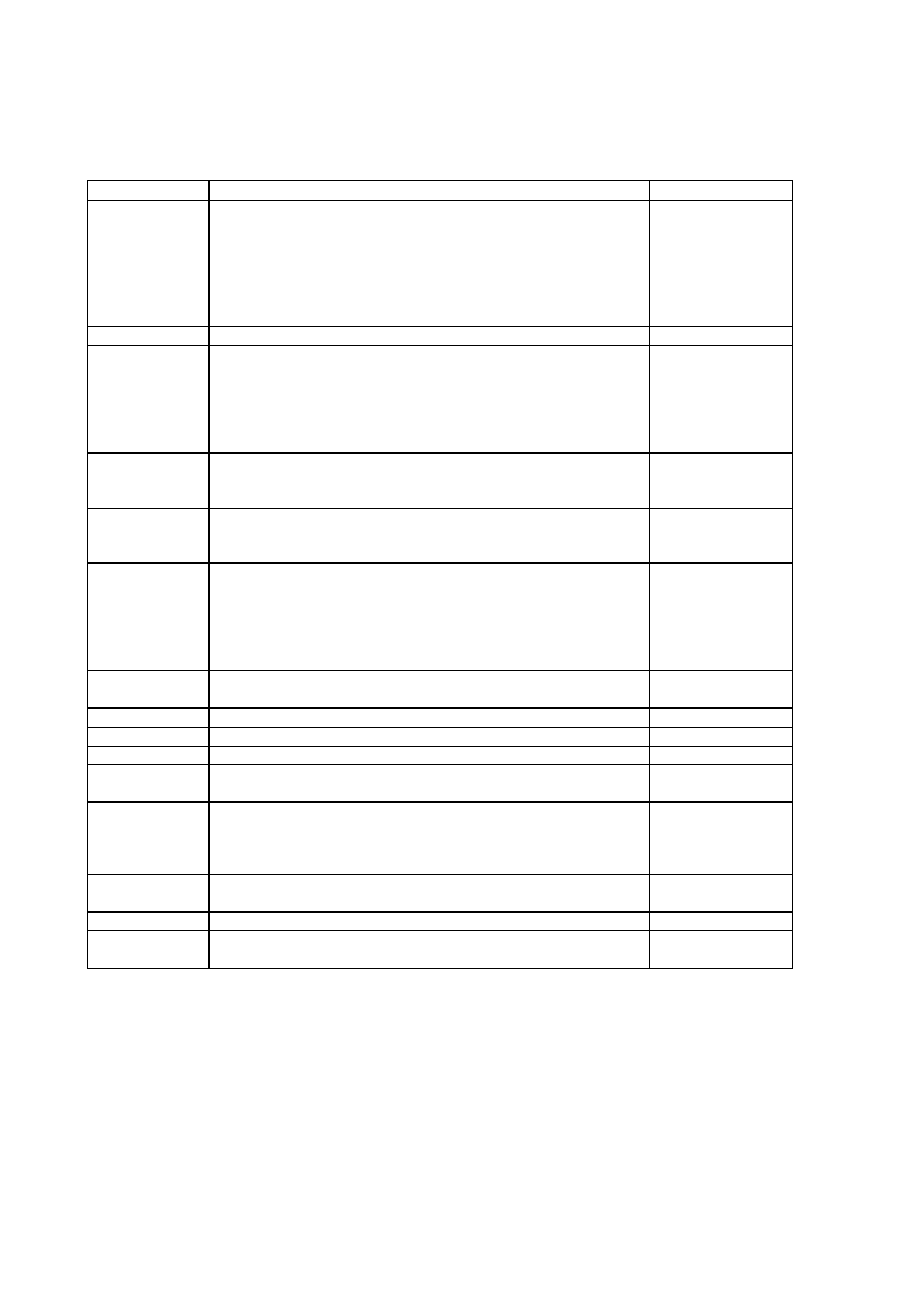
Table 2
Receiving Rules
Field name
Description
Default
Type
Defines the message output format. This information will be
used by other parts of the program to parse and display the
data. If you are using a format that you cannot find in the
list, type "Other".
|xx.x|xx.x|xx.x|
(| = any
delimiter), Plain
Text, WAT11,
DDP25, CT25K
Msg1, PWD11
Msg2, Other.
Length
The maximum length of a received data message.
200 characters
Timeout, sec
The maximum time Receiver waits for the end of a data
message after receiving the start characters.
Note that the timeout interval must be longer than the
interval between consecutive messages! When timeout is
detected, the numeric field is changed to NaN (= not a
number).
125 seconds
Start chars
The first characters that must be received by the computer
to determine the start of a new message. Control characters
are defined in hex format.
\01PTU\02
End chars
The end characters in the received message that tell the
computer that the current message is over. Control
characters are defined in hex format.
\03\r\n
\01
is
\02
is
\03
is
AA
is
\r
is
\n
is
Path
If the path is defined, the message body will be written into
text file :
Empty
Ack
Optional acknowledgement string
Empty
Nack
Optional negative acknowledgement string
Empty
Topic
Topic name for Data Socket
Empty
E-mail
Recipients
Optional list for E-mail recipients of data messages
Empty
Item name
Defines the order and name of the variables received. Use
the scroll bars to add more names. The number of rows in
the table should be the same as values in the incoming
message.
Unit
Defines the units of the variables received. The units will
also appear on the Log data header.
Min
Optional minimum value for data.
Max
Optional maximum value for data.
Description
Optional description for data item.
Items are specified in the item table giving the sensor's name, its unit,
optional min/max limitation and description. The order of the sensors
in this list should be the same as in the incoming serial message. Any
unit conversion (for example, from m/s to knots) must be made in the
data collection equipment. The names and units defined here will be
used as the header information for logged data.