Appendix 3: hmp143a probe cable extension – Vaisala HMP140 User Manual
Page 25
HMP140A SERIES
U175en-1.5
Appendix 3
1999-12-08
1
APPENDIX 3: HMP143A PROBE CABLE EXTENSION
The cable of the HMP143A probe can be extended up to 100 metres with the
help of the extension set including a junction box (part no. 19326) and a
shielded six wire extension cable (part no. 1535).
The junction box has a 5-pole terminal block and two PG9 lead-throughs. The
extension cable is a shielded 6 x 0.22 mm
2
copper wire cable. This cable
enables the extension without the need for transmitter adjustments. The user
can also use some other cable for this purpose provided that it is a shielded
copper wire cable. A shielded cable is recommended as it ensures the best
possible EMC protection. The diameter of the cable should not exceed 7 mm
as larger cables do not fit to the lead-through of the transmitter.
The HMP143A probe head uses a combined signal ground and supply voltage
ground. Ground wire resistance R
c
causes an offset type error to the
transmitter output. The error is -0.11 x R
c
both in %RH and in °C. This means
that if maximum error allowed is e.g. -0.3 %RH or -0.3 °C, the ground wire
resistance should not exceed 2.7
Ω
. The resistance of the cable 1535 is
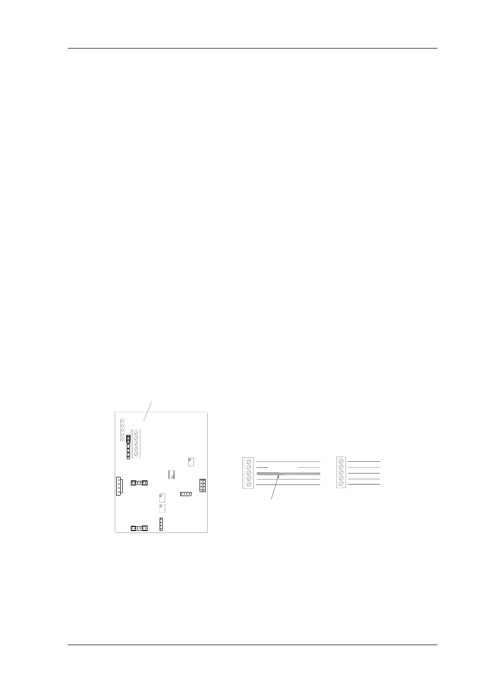
minimized by connecting three wires as a ground conductor (see Figure 1).
Possible error can also be leveled out by readjusting the transmitter offset
(RH offset and T offset).
VIO
SHIELD
GRN (ground)
YEL
BRN
HMP143 PROBE
CONNECTOR
JUNCTION
CABLE SHIELD
VIO
SHIELD
GRN
YEL
BRN
PROBE CONNECTOR
BOX
EXTENSION
CABLE
BLU
GREY
YEL
BLK
HMP143 CABLES
THREE WIRES CONNECTED
TOGETHER (WHT, GRN, RED)
PROBE CONNECTOR ON THE
HMP143 PCB; THE COLOURS
SHOW THE DIRECT CONNECTION
OF THE HMP143 PROBE HEAD
Figure 1
Schematic of the extension set connections