4 connectors and potentiometers on the main pcb, Figure 3.5 jumper positions for voltage outputs – Vaisala HMP140 User Manual
Page 11
HMP140A SERIES
U175en-1.5
Operating Manual
1999-12-08
7
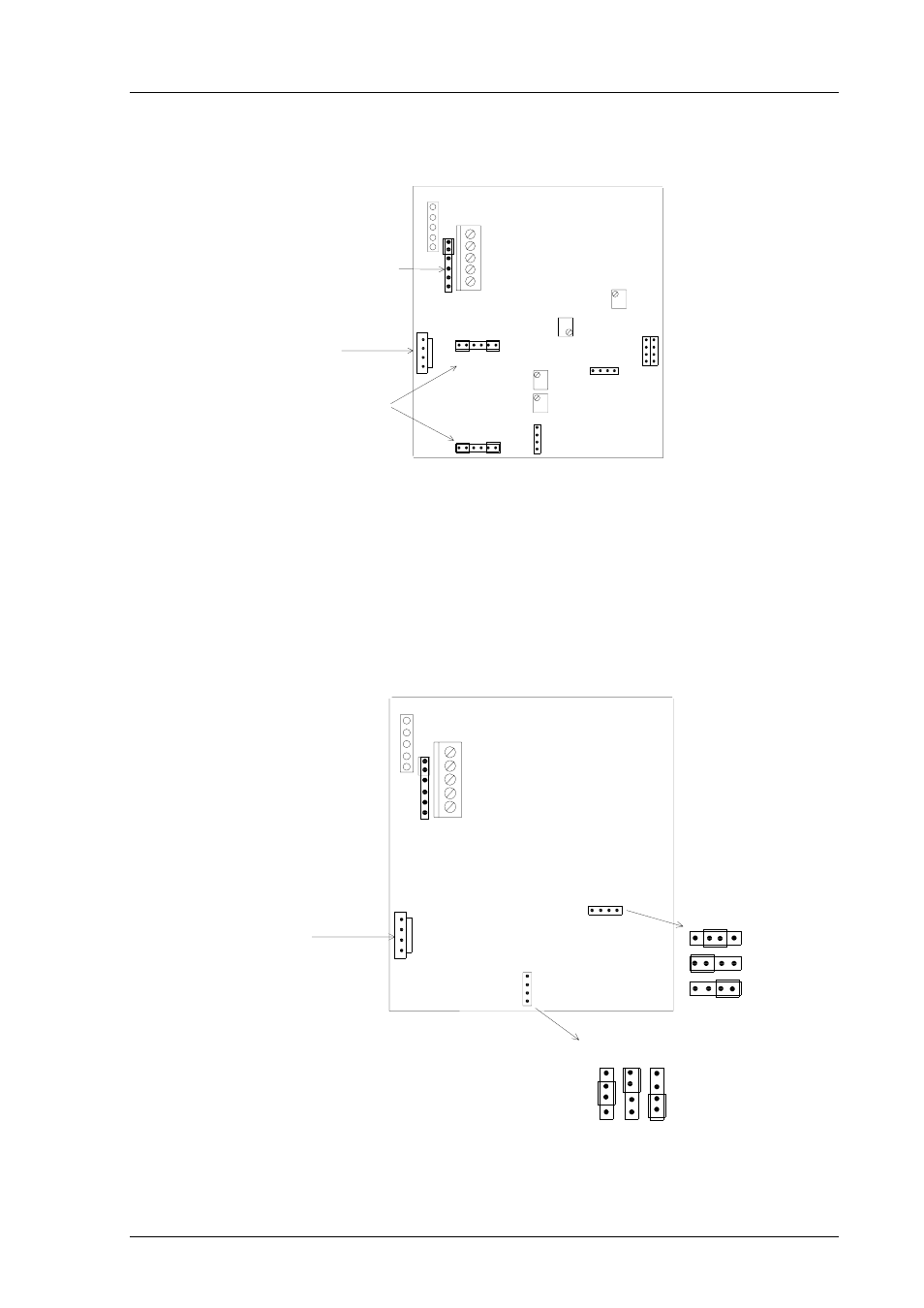
3.4
Connectors and potentiometers on the main PCB
DISPLAY CONNECTOR
Tgain
Toffset
Toutput
selection
RHoffset
RHgain
RHoutput
VIO
SHIELD
GRN
YEL
BRN
X15
X16
PROBE CONNECTOR
selection
Test connector
for factory use;
leave the jumper
as indicated here
Test connector for
one point calibration
Spare
jumpers
Connectors
for the
current module
Figure 3.4
Connectors and potentiometers on the main PCB
3.5
Selecting the outputs
The HMP140A series transmitters can be ordered with the desired output
signals already selected. If the outputs are changed, the jumpers have to be
moved to corresponding places (see Figure 3.5). For current outputs, see
Appendix 1. Jumper changes may change the output <
±
0.15 %FS within the
chosen range; this usually does not give cause to recalibration.
DISPLAY CONNECTOR
Toutput
selection
RHoutput
VIO
SHIELD
GRN
YEL
BRN
Toutput selection
0-1V
0-5V
0-10V
Voltage
PROBE CONNECTOR
selection
0-1V
0-5V
0-10V
RHoutput selection
Voltage
Test connector for
one point calibration
Figure 3.5
Jumper positions for voltage outputs