Temperature calibration of a dewpoint module, Two sensor heads, Figure 6 – Vaisala HMM211 User Manual
Page 27: Offset and gain calibration examples
Chapter 5 _______________________________________________________________ Calibration
°C
°C
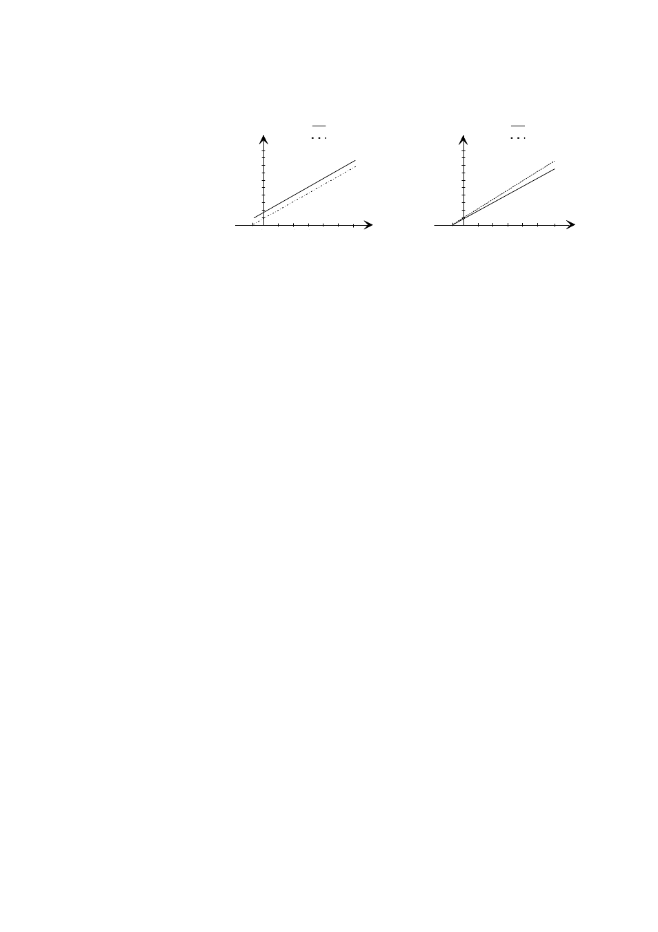
offset correction
gain correction
voltage range
(for example, 0 ... 5 V)
voltage range
(for example, 0 ... 5 V)
before correction
after gain correction
after offset correction
before correction
-20
20
40
60
80 100 120
-20
20
40
60
80 100
120
Figure 6
Offset and Gain Calibration Examples
3.
After having performed the calibration, disconnect the jumper.
Temperature Calibration of a Dewpoint
Module
1.
The warming function must be deactivated by connecting a jumper
to the T offset or T gain calibration pins (see Figure 5 on page 25).
The temperature signal is now on Channel 2 (previously Td signal).
Note that the chosen output range corresponding to -70 ... +180 °C
is now scaled on this channel. For example, if the Td output range
is 0 ... 5 V, the T output during calibration is 0 ... 5 V < > -70 ...
+180 °C (-94 ... +356 °F).
2.
Allow enough time for the instruments to stabilize to the same
temperature.
3.
Adjust the reading with UP and DOWN switches (see Figure 5 on
page 25). Note that during gain adjustment, the offset point
(-70 °C) does not change (see Figure 6 above).
4.
After having performed the calibration, disconnect the jumper.
Temperature Calibration of an RH and T
Module with Two Sensor Heads
1.
Connect a jumper to the T offset or T gain calibration pins (see
Figure 5 on page 25). The temperature signal of the humidity probe
is now on Channel 1 (previously RH signal). Note that the chosen
output range corresponding to -70 …+180 °C is now scaled on this
channel, for example if the RH output range is 0 ... 5 V, the T
output during calibration is 0 ... 5 V < > -70 ... +180 °C (-94 …
+356 °F).
VAISALA _______________________________________________________________________ 27