Communication parameters, Addressing – Vaisala HMM105 User Manual
Page 6
Technical Reference _________________________________________________________________
4 _________________________________________________________________ M211638EN-A
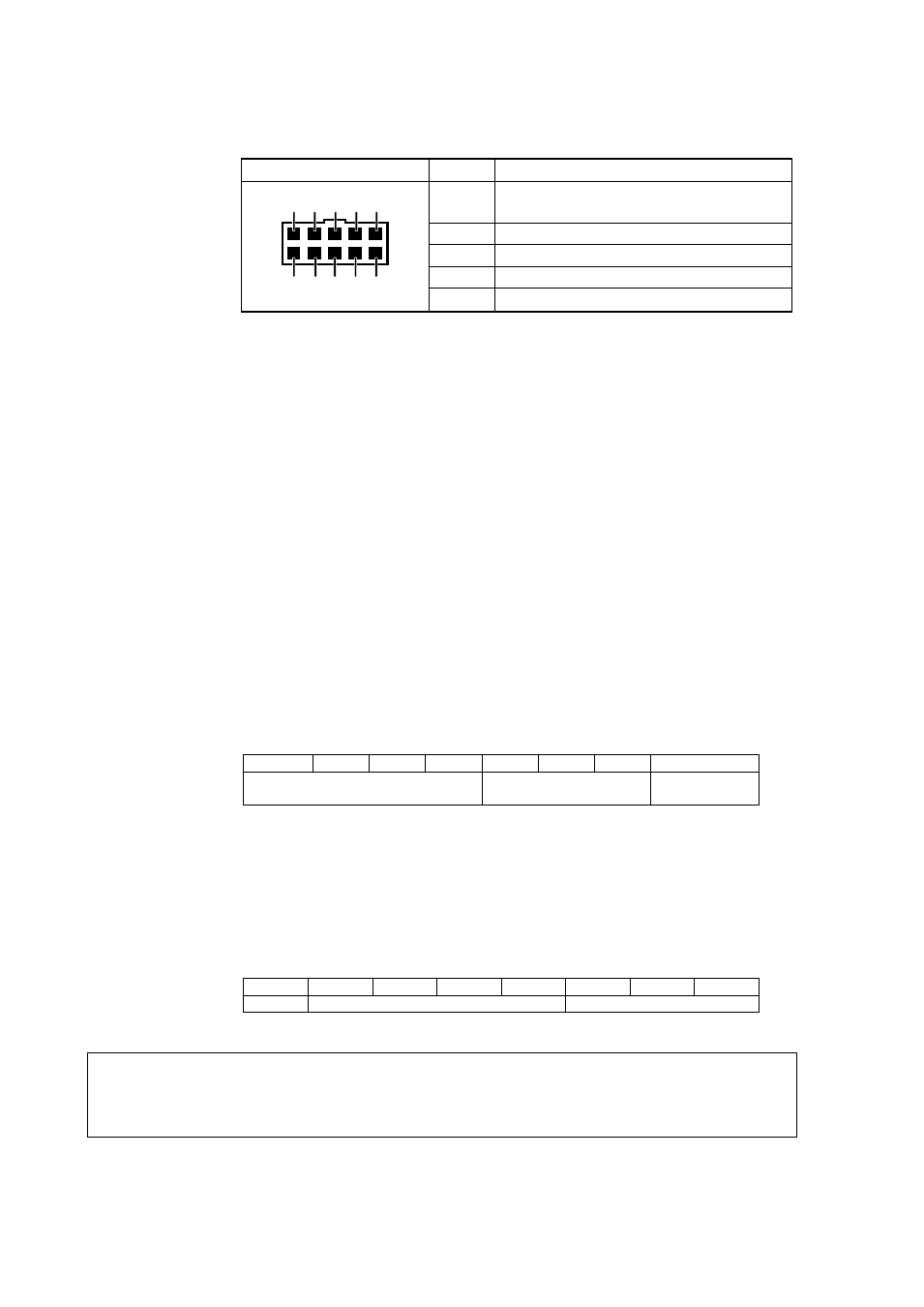
Table 3
HMM105 Signal and Power Connector X6
Connector Pinout
Pin #
Function
6, 8
Supply voltage input
10 ... 35 VDC or 24 VAC
5, 7
Ground
1, 3
5 V I
2
C bus SDA
2, 4
5 V I
2
C bus SCL
9, 10
Not connected
Communication Parameters
HMM105 supports a maximum clock speed of 50 kHz. Protocol bits are
sent most significant bit (MSB) first. Parameter bytes are sent using little
endian order.
Addressing
HMM105 uses 7-bit addressing. The address consists of:
- 4-bit device type identifier part (default “0101” for HMM105)
- 3-bit sub address (default “111”)
The full 7-bit default address is “0101111” (2Fh). In I
2
C communication,
the address should be provided by the master in the standard way after
the I
2
C start condition, with the read/write bit as the least significant bit
(LSB).
Table 4
HMM105 I
2
C Address
0
1
0
1
1
1
1
R/W
Device type
Sub-address
Read/write bit
(LSB)
The I
2
C implementation of the HMM105 also includes the address inside
the message frame. The purpose of this is to make the I
2
C
implementation easier, since the I
2
C address can be lost by the I
2
C
hardware. This address is provided without the read/write bit, with zero
as the most significant bit (MSB).
Table 5
HMM105 Device Address
0
0
1
0
1
1
1
1
MSB
Device type
Sub-address
NOTE
Make sure there are no addressing conflicts if other I
2
C devices are put
on the same bus. The HMM105 address can be changed, see Table 32 on
2
4
6
8
10
1
3
5
7
9