Vaisala HMD70 User Manual
Page 9
HMD70U/Y Transmitters
U303en-1.1
Operating Manual
1997-07-31
5
3.4
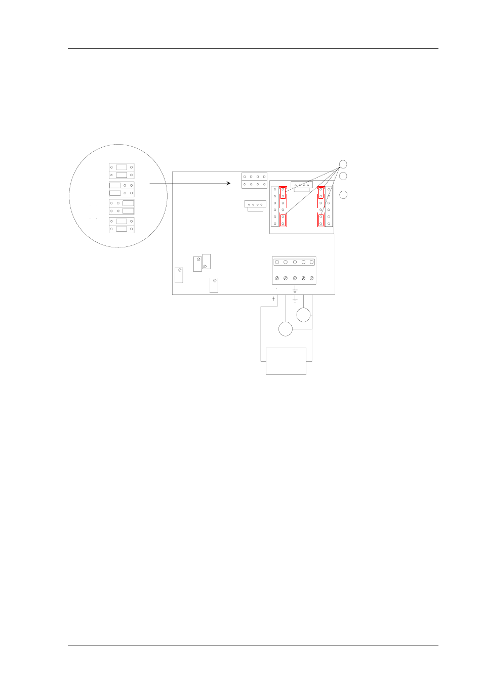
Electrical connections and installation of the current module
Figure 3.4 shows the electrical connections and the installation of the current
module.
INSTALLATION OF
THE CURRENT MODULE 18945HM
1. Take off the jumpers
2. Connect the module; note the
right direction!
3. Connect the power supply
OUTPUT SELECTIONS
0...1V
0...5V
0...10V
0...20mA
current
module
T
RH
RH
RH
RH
T
T
T
T
RH
TEST
CONNECTOR
1
1
1
1
2
3
4 5
current module 0...20 mA
U
U
U
U
RH OFFSET
T OFFSET
Us
RH
out
T
out
GND
V/mA
DC/AC
power supply
V/mA
RH GAIN
T GAIN
Figure 3.4
Electrical connections and installation of the current
module
See also other documents in the category Vaisala Humidifiers:
- Calibration of Digital Transmitters with HMI41 (36 pages)
- Calibration of Series HMDW2030 and HMP130 Transmitter with HMI41 (14 pages)
- Calibration of Series HMDW6070 and HMP140 Transmitter with HMI41 (30 pages)
- HM34 (30 pages)
- HM40 (47 pages)
- HM44 (52 pages)
- HM70 (83 pages)
- HMD40 (1 page)
- HMD60 (4 pages)
- HMDW110 (62 pages)
- HMDW80 (51 pages)
- HMI41 (74 pages)
- HMP41 (72 pages)
- HMK15 (39 pages)
- HMM100 (71 pages)
- HMM105 (23 pages)
- HMM211 (42 pages)
- HMM212 (36 pages)
- HMM213 (52 pages)
- HMP140 (28 pages)
- HMP155 (84 pages)
- HMP228 (115 pages)
- HMP230 (163 pages)
- HMP240 (130 pages)
- HMP260 (118 pages)
- HMP60 (71 pages)
- HMT100 (52 pages)
- HMT120 (87 pages)
- HMT130 (95 pages)
- HMT140 (76 pages)
- HMT310 (88 pages)
- HMT310 (105 pages)
- HMT330 (209 pages)
- HMT360 (97 pages)
- HMT360 (63 pages)
- HMT360N (110 pages)
- HMW40 (1 page)
- HMW90 (110 pages)
- SHM40 (68 pages)
- RDP100 (14 pages)