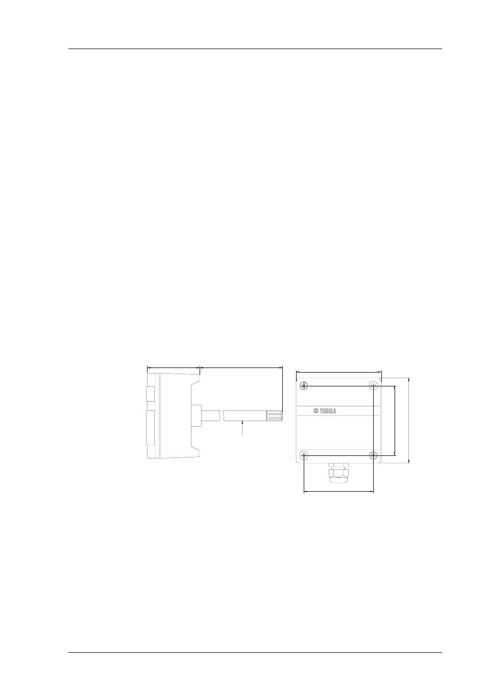
Installation, Figure 3.2 dimensions of the hmd70u/y (in mm) – Vaisala HMD70 User Manual
Page 7
HMD70U/Y Transmitters
U303en-1.1
Operating Manual
1997-07-31
3
3.
INSTALLATION
3.1
Selecting the place of installation
Select a place that gives a true picture of the environment or process and is as
clean as possible. Air should circulate freely around the sensor. A rapid air
flow is recommended as it ensures the same temperature for the ambient air
and the sensor head.
Install the transmitter in a place where no cold or hot spot can develop. If the
sensor head is installed in a duct or channel where the temperature is different
from the ambient temperature, insulate the point of entry. An uninsulated
installation might lead to condensation on the sensor head and even if no
condensation occurs, the resultant air flow may change the temperature near
the sensor head and distort the readings.
3.2
Mounting
Mount the transmitter with two screws. Place the drilling template on the duct
surface and drill the holes as indicated. Remember to drill an additional hole
for calibration purposes.
Ø 12 (0.47)
250 (9.84)
62 (2.44)
<<< Mounting hole
82 (3.23)
100 (3.94)
>
>
>
100 (
3
.9
4)
82 (
3
.23)
Mo
unt
ing
hol
e
Figure 3.2
Dimensions of the HMD70U/Y (in mm)