Parent, Connector of the “ child-1 ” unit to the, Wrong connection between the – State GTS-710-PIEA User Manual
Page 27: Child-1, Unit and the, Child-2, Unit prohibited wrong connection between the, Unit wrong connection between the, Unit parent unit child-1 unit, Parent unit child-1 unit child-2 unit
- 27 -
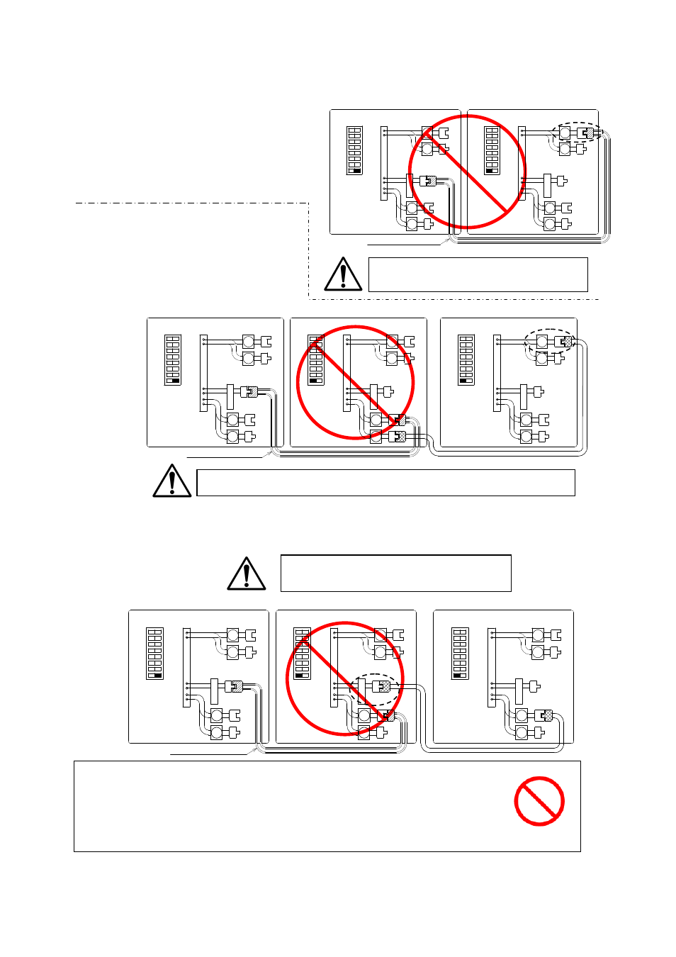
CAUTION
If you connect the “PARENT” connector
of the “PARENT” unit to the “[3]”
connector of the “CHILD-1” unit, the
“PARENT” unit and the “CHILD-1”unit
will display “761” error code.
If you connect the “[2]” connector of
the “CHILD-1”unit to the “[3]”
connector of the “CHILD-2” unit, the
“PARENT” unit and the “CHILD-2”unit
will display “761” error code.
If you connect the
“
PARENT
”
connector of the “CHILD-1” unit to the
“
[1]
”
connector of the
“CHILD-2” unit, the “CHILD-2” unit will work as an individual unit, and will not be part of the
Easy-Link system.
WARNING
Connecting two “PARENT” connectors together from two separate units may
damage the computer board. The communication cable has a female end
and a male end so it’s impossible to have a PARENT -to- PARENT connection
with the communication cable. Do not splice or modify connectors.
Wrong connection between the
“
CHILD-1
”
unit and the
“
CHILD-2
”
unit
Prohibited
Wrong connection between the
“
CHILD-1
”
unit and the
“
CHILD-2
”
unit
Wrong connection between the
“
PARENT
”
unit and the
“
CHILD-1
”
unit
PARENT unit
CHILD-1 unit
Communication cable
2
1
2
1
3
4
3
4
2
1
2
1
3
4
3
4
C o n n e c t o r s
O
F
F
O
N
O
F
F
O
N
C o n n e c t o r s
O
F
F
O
N
O
F
F
O
N
1
2
3
4
5
6
7
8
Left bank of
Dipswitches
1
2
3
4
5
6
7
8
Left bank of
Dipswitches
P
A
R
E
N
T
P
A
R
E
N
T
PARENT unit
CHILD-1 unit
CHILD-2 unit
Communication cable
2
1
2
1
3
4
3
4
2
1
2
1
3
4
3
4
2
1
2
1
3
4
3
4
C o n n e c t o r s
O
F
F
O
N
O
F
F
O
N
C o n n e c t o r s
O
F
F
O
N
O
F
F
O
N
C o n n e c t o r s
O
F
F
O
N
O
F
F
O
N
1
2
3
4
5
6
7
8
Left bank of
Dipswitches
P
A
R
E
N
T
1
2
3
4
5
6
7
8
Left bank of
Dipswitches
P
A
R
E
N
T
1
2
3
4
5
6
7
8
Left bank of
Dipswitches
P
A
R
E
N
T
PARENT unit
CHILD-1 unit
CHILD-2 unit
Communication cable
2
1
2
1
3
4
3
4
2
1
2
1
3
4
3
4
2
1
2
1
3
4
3
4
C o n n e c t o r s
O
F
F
O
N
O
F
F
O
N
C o n n e c t o r s
O
F
F
O
N
O
F
F
O
N
C o n n e c t o r s
O
F
F
O
N
O
F
F
O
N
1
2
3
4
5
6
7
8
Left bank of
Dipswitches
1
2
3
4
5
6
7
8
Left bank of
Dipswitches
1
2
3
4
5
6
7
8
Left bank of
Dipswitches
P
A
R
E
N
T
P
A
R
E
N
T
P
A
R
E
N
T