Connector of the “ child-1 ” unit to the, Connector of the “ child-2 ” unit to the, Parent unit child-1 unit – State GTS-710-PIEA User Manual
Page 25
- 25 -
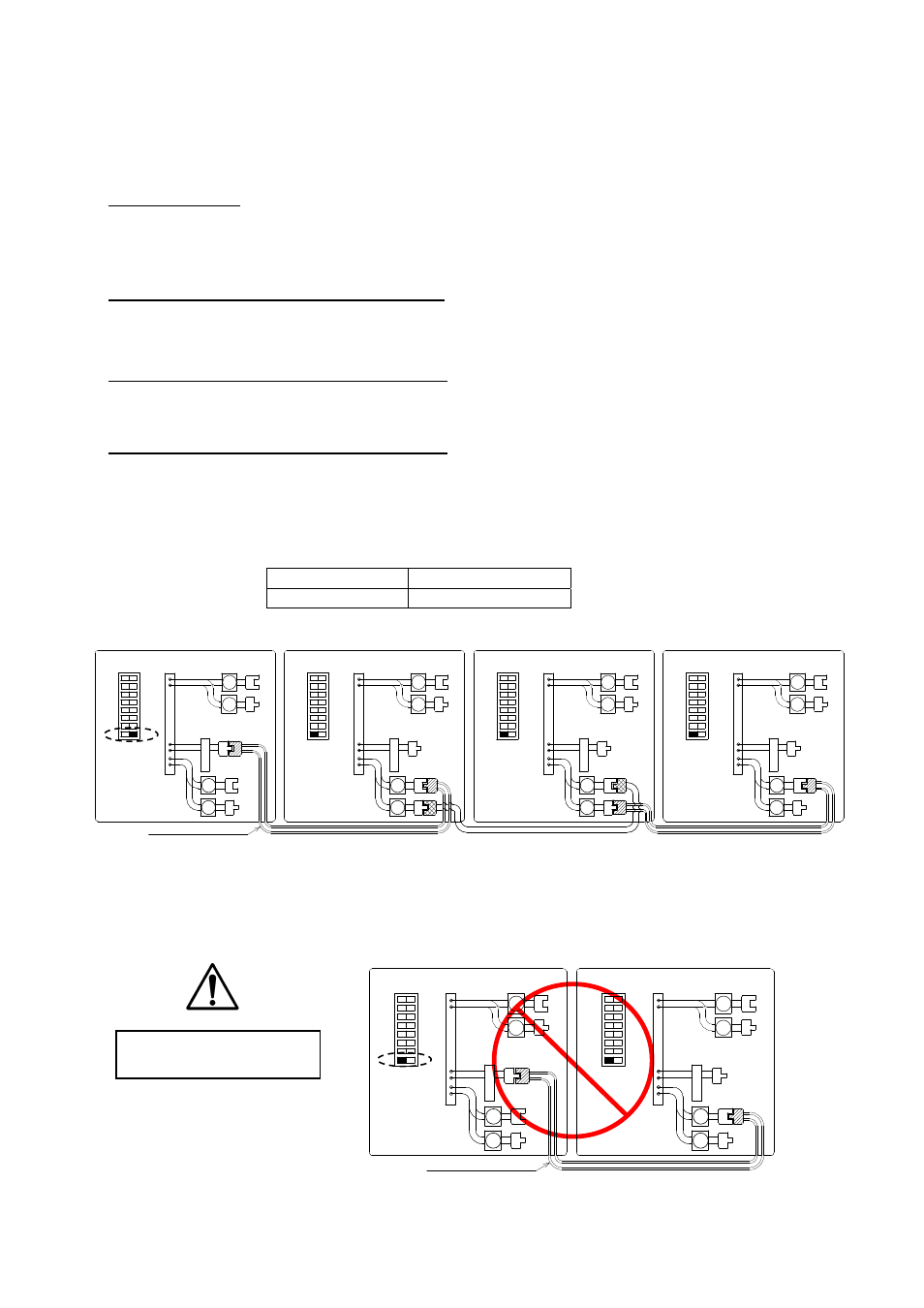
Easy-Link Connection Procedures
1. Choose one of your units as the “PARENT” unit.
2. “The PARENT”
Locate the left bank of dipswitches to the lower of the 7-seg. LED on the computer board of
the unit that you select to be the “PARENT” unit. Change dipswitch No. 8 to “ON”. Do not
change any of the dipswitches on the “CHILD” units.
3. Between the “PARENT” and the “CHILD-1”
Connect the “PARENT” connector of the “PARENT” unit to the
“
[1]
”
connector of the “CHILD-
1” unit.
4. Between the “CHILD-1” and the “CHILD-2”
Connect the
“
[2]
”
connector of the “CHILD-1” unit to the
“
[1]
”
connector of the “CHILD-2” unit.
5. Between the “CHILD-2” and the “CHILD-3”
Connect the
“
[2]
”
connector of the “CHILD-2” unit to the
“
[1]
”
connector of the “CHILD-3” unit.
6. Make sure the “7-seg LED” of all the units’ computer boards display the unit #. The
numbering system automatically allocates the unit # to each water heater in the Easy-Link
system, in accordance with the table below.
PARENT unit
Unit # : 1
CHILD units
Unit# : 2, 3 and 4
CAUTION
Unless you change dipswitch No. 8 of the “PARENT” unit to “ON”, the system will not
work as an Easy-Link system. The units will work as individual units.
Wrong dipswitch setting on
the “PARENT” unit
The dark squares indicate the direction
the dipswitches should be set to.
PARENT unit
CHILD-1 unit
CHILD-2 unit
CHILD-3 unit
Communication cable
C o n n e c t o r s
2
1
2
1
O
F
F
O
N
1
2
3
4
5
6
7
8
Left bank of
Dipswitches
O
F
F
O
N
3
4
3
4
2
1
2
1
3
4
3
4
2
1
2
1
3
4
3
4
2
1
2
1
3
4
3
4
C o n n e c t o r s
C o n n e c t o r s
C o n n e c t o r s
1
2
3
4
5
6
7
8
O
F
F
O
N
O
F
F
O
N
Left bank of
Dipswitches
Left bank of
Dipswitches
O
F
F
O
N
O
F
F
O
N
1
2
3
4
5
6
7
8
Left bank of
Dipswitches
O
F
F
O
N
O
F
F
O
N
1
2
3
4
5
6
7
8
P
A
R
E
N
T
P
A
R
E
N
T
P
A
R
E
N
T
P
A
R
E
N
T
Communication cable
C o n n e c t o r s
P
A
R
E
N
T
2
1
2
1
1
2
3
4
5
6
7
8
3
4
3
4
2
1
2
1
3
4
3
4
O
F
F
O
N
O
F
F
O
N
C o n n e c t o r s
O
F
F
O
N
O
F
F
O
N
1
2
3
4
5
6
7
8
P
A
R
E
N
T
Left bank of
Dipswitches
Left bank of
Dipswitches
PARENT unit
CHILD-1 unit