Gas water heaters, Service instructions – State GPH-90N User Manual
Page 61
Service Instructions
0610
61
319172-000 Rev. 00
GAS WATER HEATERS
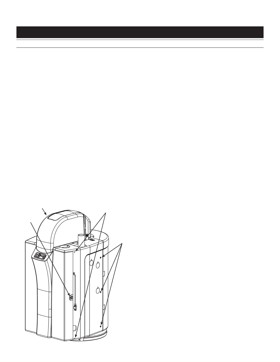
Remove panels to gain access:
Door opening
Unlock the door by rotating the lock counter-clockwise
with a wide, slot screwdriver.
Release the top and bottom door pins by prying the pins
out, using a small screwdriver.
Open the door (the door remains fastened to the left
side panel).
To Remove:
Disconnect the electrical power to the water heater.
Close the shutoff valve on the gas supply line to the
water heater.
Close the shutoff valves on both the hot-water and cold-
water lines.
Drain the tank following the instructions in the “Draining
The Tank” section in the Operating Manual.
1.
2.
3.
1.
2.
3.
4.
Remove the ten screws that secure the front cover of
the heat engine. Remove the front cover of the Heat
Engine.
Remove the two screws securing the circuit board and
partially extract it.
Carefully disconnect the HiLimit temperature switch (2
thin red wires) and the Blower motor wiring harness plug
from the circuit board.
Carefully disconnect the (black) wire from the Spark
generator to the electrode.
Remove the two screws securing the retaining clip that
holds in the copper tube to the fi tting on the left side of
the heat engine.
Remove the retaining clip.
Remove the two screws securing the retaining clip that
holds in the copper tube to the internal fl ow valve at the
lower right side of the heat engine.
Remove the retaining clip.
Carefully disconnect the blue wire from the Flame
sensor.
Remove the two screws securing the ECO switch.
Remove the ECO switch.
Remove the four screws around the outside of the orifi ce
plate. One of these screws also secures the Spark
generator, another one secures a ground lug.
Remove the fi ve screws that secure the top portion of
the Gas valve to the burner chamber.
Remove the four retaining screws that secure the heating
core to the Heat Engine Cabinet. There is one under the
blower, one under the combustion chamber and one on
each side at the top. Note: When removing the upper
two screws support the core so that it will not drop.
Remove the Heat exchanger assembly from the Heat
engine.
Remove the exhaust gasket and ring.
Remove six screws securing the Combustion chamber
to the lower portion of Heat exchanger.
Remove the Combustion chamber.
Remove the six screws securing the Draft hood to the
upper portion of Heat exchanger.
Remove the Draft hood.
Carefully remove and retain (but do NOT cut!) the HiLimit
temperature switch from the heat exchanger.
Ensure old (white) gasket is completely removed and
no material remains on the Draft Hood and Combustion
chamber.
5.
6.
7.
8.
9.
10.
11.
12.
13.
14.
15.
16.
17.
18.
19.
20.
21.
22.
23.
24.
25.
26.
HEAT EXCHANGER REPLACEMENT
This instruction has been prepared to acquaint you with the service of your gas-fi red water heater. It is your responsibility to
ensure that your water heater is properly installed and maintained.
Failure to follow the instructions in this service instruction sheet may result in serious bodily injury and/or property
damage. Thoroughly read and understand all instructions before you attempt to install, operate or service this heater.
Maintenance and service requires trade knowledge in the areas of plumbing, electricity and gas. If you lack these skills or
have diffi culty understanding these instructions you should not proceed. Enlist the help of a qualifi ed service technician to
service this water heater.
Access To
Door Pins
Door
Lock
Screws
Top Casing
(Front)