Gas water heaters, Service instructions – State GPH-90N User Manual
Page 57
Service Instructions
0610
57
319172-000 Rev. 00
GAS WATER HEATERS
TANK REPLACEMENT
This instruction has been prepared to acquaint you with the service of your gas-fi red water heater. It is your responsibility to
ensure that your water heater is properly installed and maintained.
Failure to follow the instructions in this service instruction sheet may result in serious bodily injury and/or property
damage. Thoroughly read and understand all instructions before you attempt to install, operate or service this heater.
Maintenance and service requires trade knowledge in the areas of plumbing, electricity and gas. If you lack these skills or
have diffi culty understanding these instructions you should not proceed. Enlist the help of a qualifi ed service technician to
service this water heater.
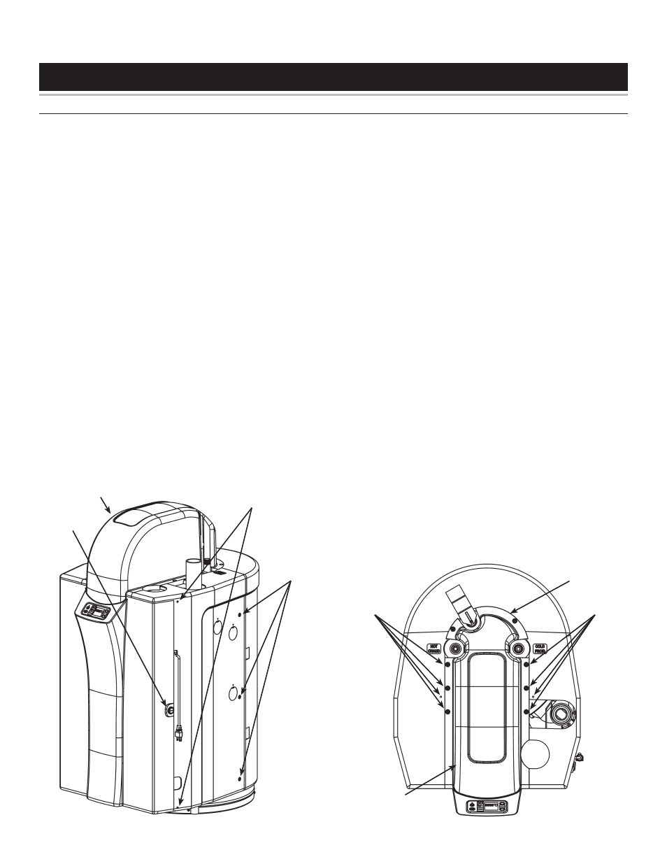
Remove panels to gain access:
Remove Door
Disconnect the electrical power to the water heater.
Unlock the door by rotating the lock counter-clockwise
with a wide, slot screwdriver.
Release the top and bottom door pins by prying the pins
out, using a small screwdriver.
Open the door (the door remains fastened to the left
side panel).
Carefully disconnect all the wiring harness plugs from
the Display Panel.
Carefully remove the door hinge pins from their retaining
fi ngers.
Remove the top casing (front)
Use a screwdriver to remove the six screws securing
the top casing.
Lift up and remove casing top (front).
1.
2.
3.
4.
5.
6.
1.
2.
Remove the top casing (rear)
Use a screwdriver to remove the two screws securing
the top casing.
Lift up and remove casing top (rear).
Remove the right side panel
Use a screwdriver to remove the screw from the bottom,
front of the right side panel.
Remove the three screws from the right side panel
towards the rear of the unit.
Remove the screw from the top of the unit.
Push the panel back and lift out.
Remove the left side panel
Use a screwdriver to remove the screw from the bottom,
front of the left side panel.
Remove the three screws from the left side panel towards
the rear of the unit.
Remove the screw from the top of the unit.
Push the panel back and lift out.
Remove the rear panel
Use a screwdriver to remove the four screws on the
back side
Lift off the panel.
1.
2.
1.
2.
3.
4.
1.
2.
3.
4.
1.
2.
Access To
Door Pins
Door
Lock
Screws
Top Casing
(Front)
Screws
Screws
Top
Casing (Front)
Top
Casing (Rear)