Gas water heaters, Service instructions – State GPH-90N User Manual
Page 15
Service Instructions
0610
15
319172-000 Rev. 00
GAS WATER HEATERS
INTERNAL FLOW VALVE REPLACEMENT
This instruction has been prepared to acquaint you with the service of your gas-fi red water heater. It is your responsibility to
ensure that your water heater is properly installed and maintained.
Failure to follow the instructions in this service instruction sheet may result in serious bodily injury and/or property
damage. Thoroughly read and understand all instructions before you attempt to install, operate or service this heater.
Maintenance and service requires trade knowledge in the areas of plumbing, electricity and gas. If you lack these skills or
have diffi culty understanding these instructions you should not proceed. Enlist the help of a qualifi ed service technician to
service this water heater.
To Remove:
Disconnect the electrical power to the water heater.
Close the shutoff valve on the gas supply line to the
water heater.
Close the shutoff valves on both the hot-water and cold-
water lines.
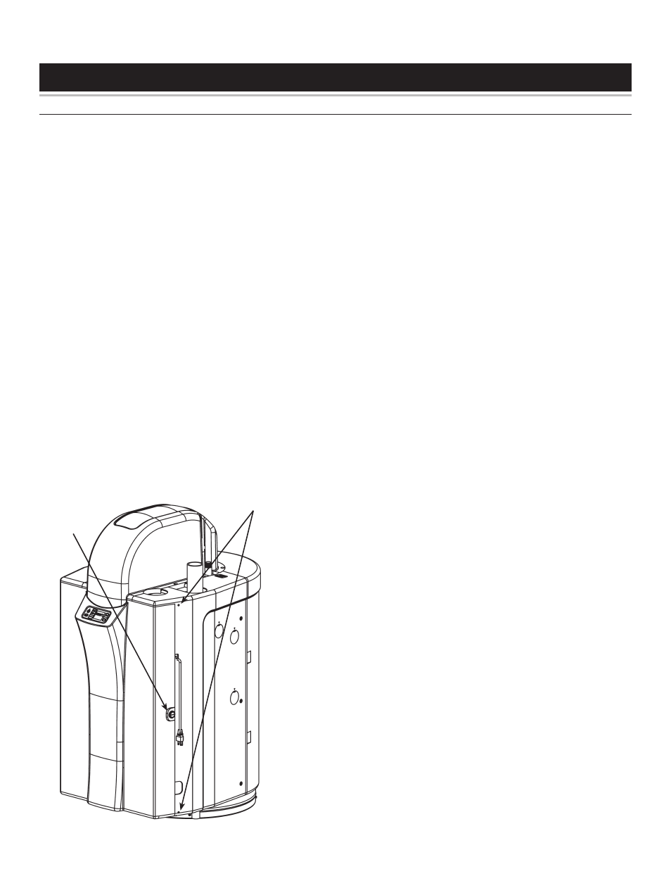
Unlock the door by rotating the lock counter-clockwise
with a wide, slot screwdriver.
Release the top and bottom door pins by prying the pins
out, using a small screwdriver.
Open the door (the door remains fastened to the left
side panel).
Remove the ten screws that secure the front cover of
the heat engine. Remove the front cover of the Heat
Engine.
Carefully disconnect the three wire harness plugs leading
to fl ow valve. Two are for Flow Valve control, one is for
the Inlet Thermistor.
1.
2.
3.
4.
5.
6.
7.
8.
Drain the tank following the instructions in the “Draining
The Tank” section in the Operating Manual.
Remove the two screws that fasten the copper piping to
the Circulation Pump (discharge side).
Remove the two screws from the fl ange on the outlet
side of the fl ow valve and remove the clamp.
Remove the two screws fastening the fl ow valve mounting
bracket to the Heat Engine Cabinet.
Remove the two screws fastening the copper piping to
the fl ow valve mounting bracket.
Remove the two screws fastening the fl ow valve to the
mounting bracket.
Remove the Internal Flow Valve.
To Install:
Secure the new Internal Flow Valve to the mounting
bracket with the two fl ow valve mounting screws.
Secure the copper piping to the fl ow valve mounting
bracket using the two copper piping mounting screws.
Secure the mounting bracket with two screws.
Secure the piping for the outlet side of the fl ow valve with
the clamp and two screws.
Secure the copper piping to the Circulation Pump
(discharge side) with two screws.
Carefully reconnect the three wire harness plugs.
Open the shutoff valves on both the hot-water and cold-
water lines.
Fill the tank following the instructions in the “Filling The
Water Heater” section in the Operating Manual.
Reassemble the front cover of the Heat Engine.
Close and lock the door.
Open the shutoff valve on the gas supply line to the
water heater.
Reconnect the electrical power to the water heater.
Restart the water heater following the “Lighting
Instructions” found in the Operating Manual.
9.
10.
11.
12.
13.
14.
15.
1.
2.
3.
4.
5.
6.
7.
8.
9.
10.
11.
12.
13.
Access To
Door Pins
Door
Lock