State GS6 75 URRBS User Manual
Page 9
9
COMBUSTION AIR AND VENTILATION FOR
APPLIANCES LOCATED IN UNCONFINED SPACES
UNCONFINED SPACE is space whose volume is not less than
50 cubic feet per 1,000 Btu per hour (4.8 m
3
per kW) of the aggregate
input rating of all appliances installed in that space. Rooms
communicating directly with the space in which the appliances are
installed, through openings not furnished with doors, are considered
a part of the unconfi ned space.
In unconfi ned spaces in buildings, infi ltration may be adequate to provide
air for combustion, ventilation and dilution of fl ue gases. However, in
buildings of tight construction (for example, weather stripping, heavily
insulated, caulked, vapor barrier, etc.), additional air may need to
be provided using the methods described in “Combustion Air and
Ventilation for Appliances Located in Confi ned Spaces.”
COMBUSTION AIR AND VENTILATION FOR
APPLIANCES LOCATED IN CONFINED SPACES
CONFINED SPACE is a space whose volume is less than 50 cubic
feet per 1,000 Btu per hour (4.8 m
3
per kW) of the aggregate input
rating of all appliances installed in that space.
A. ALL AIR FROM INSIDE BUILDINGS: (See Figures 4 and 5)
The confi ned space shall be provided with two permanent openings
communicating directly with an additional room(s) of suffi cient
volume so that the combined volume of all spaces meets the
criteria for an unconfi ned space. The total input of all gas utilization
equipment installed in the combined space shall be considered in
making this determination. Each opening shall have a minimum
free area of one square inch per 1,000 Btu per hour (22 cm
2
/kW) of
the total input rating of all gas utilization equipment in the confi ned
space, but not less than 100 square inches (645 cm
2
). One opening
shall commence within 12” (30 cm) of the top and one commencing
within 12” (30 cm) of the bottom of the enclosures.
FIGURE 5.
B. ALL AIR FROM OUTDOORS: (See Figures 6, 7 and 8)
The confined space shall be provided with two permanent
openings, one commencing within 12” (30 cm) of the top and one
commencing within 12” (30 cm) from the bottom of the enclosure. The
openings shall communicate directly, or by ducts, with the outdoors
or spaces (crawl or attic) that freely communicate with the outdoors.
1. When directly communicating with the outdoors, each opening shall
have a minimum free area of 1 square inch per 4,000 Btu per hour
(5.5 cm
2
/kW) of total input rating of all equipment in the enclosure,
see Figure 6.
FIGURE 6.
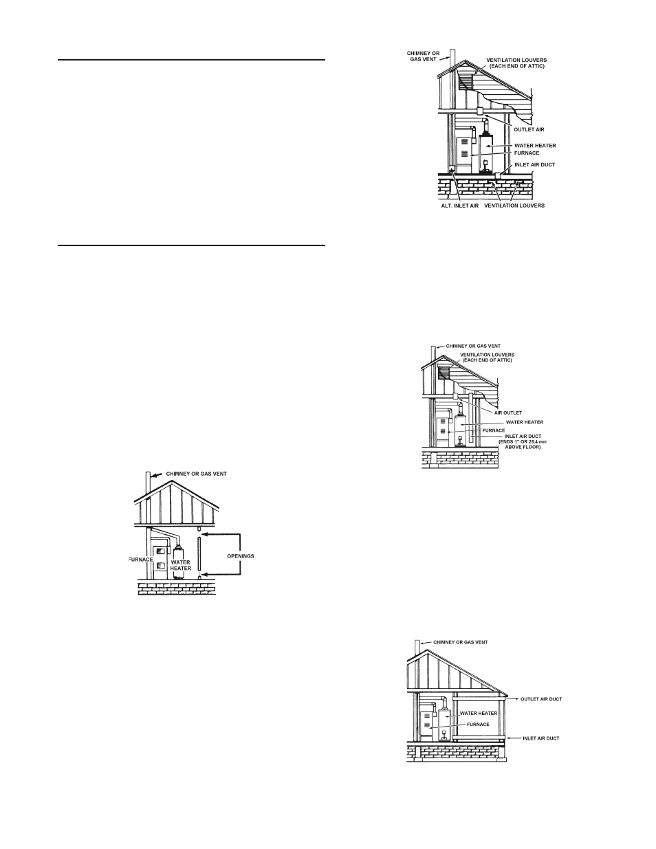
2. When communicating with the outdoors through vertical ducts,
each opening must have a minimum free area of 1 square inch
per 4,000 Btu per hour (5.5 cm
2
/kW) of total input rating of all
equipment in the enclosure, see Figure 7.
3. When communicating with the outdoors through horizontal ducts,
each opening shall have a minimum free area of 1 square inch
per 2,000 Btu per hour (11 cm
2
/kW)) of total input rating of all
equipment in the enclosure, see Figure 8.
FIGURE 7.
4. When ducts are used, they shall be of the same cross-sectional
area as the free area of the openings to which they connect. The
minimum short side dimension of rectangular air ducts shall not
be less than 3” (76.2 mm), see Figure 8.
5. Alternatively a single permanent opening may be used when
communicating directly with the outdoors, or with spaces that
freely communicate with the outdoors. The opening shall have a
minimum free area of 1 square inch per 3,000 BTU per hour (8.3
cm
2
/kW) of total input rating of all equipment in enclosure. See
Figure 8A.
FIGURE 8.