Foreword, Rough-in dimensions – State GS6 75 URRBS User Manual
Page 2
2
FOREWORD
The design of these models comply with the current edition of ANSI
Z21.10.3/CSA 4.3 an automatic storage water heater.
Installation diagrams are found in this manual. These diagrams will serve
to provide the installer with a reference for the materials and method of
piping necessary. It is highly essential that all water and gas piping be
installed as shown on the diagrams.
In addition to these instructions, the equipment shall be installed in
accordance with those installation regulations in force in the local area
where the installation is to be made. These shall be carefully followed
in all cases. Authorities having jurisdiction should be consulted before
installations are made.
The installation must conform with these instructions and the local code
authority having jurisdiction. In the absence of local codes, installations
should comply with the National Fuel Gas Code (ANSI Z223.1/NFPA
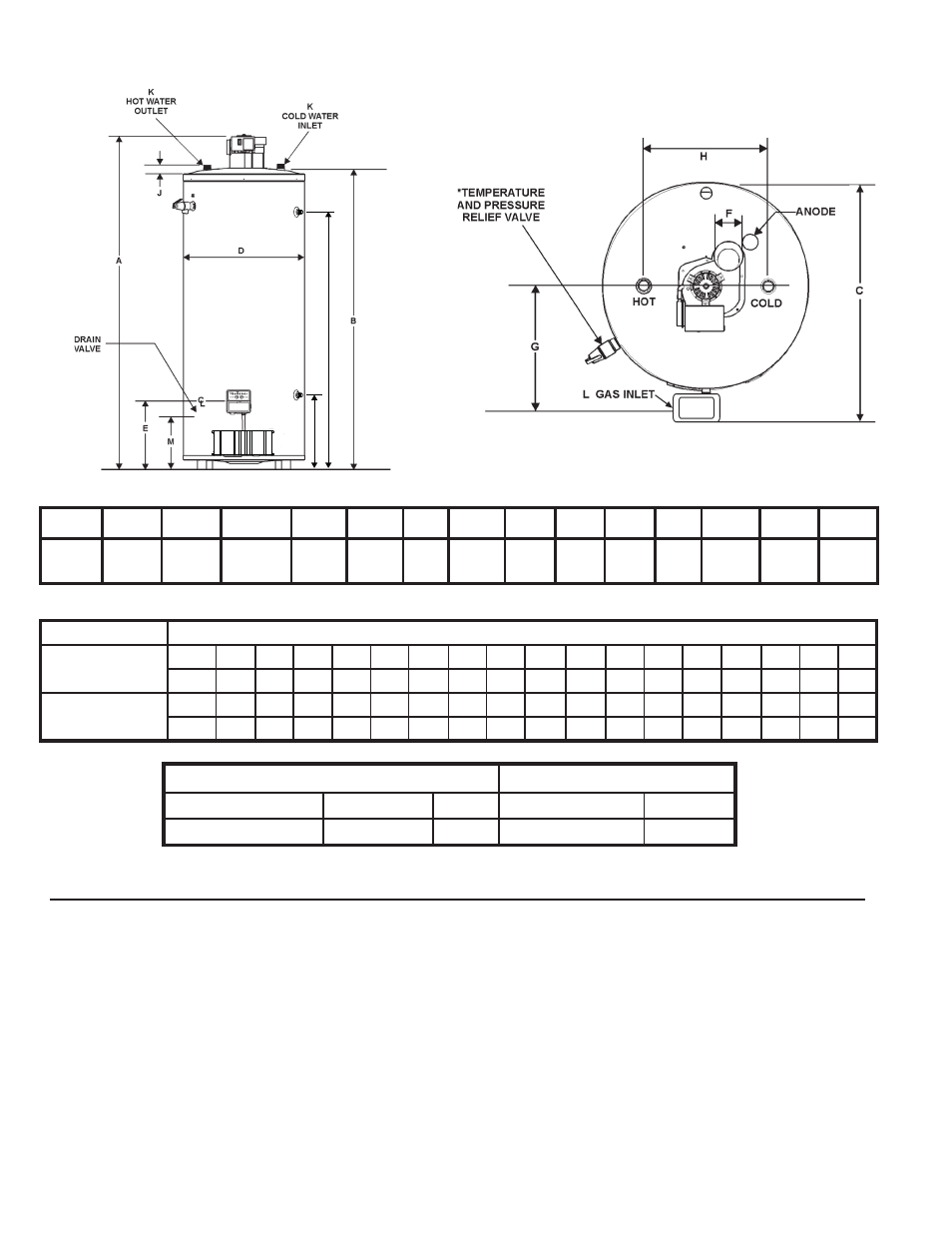
ROUGH-IN DIMENSIONS
FIGURE 1.
54) and the National Electric Code (NFPA 70). These publications are
available from The National Fire Protection Association, 1 Batterymarch
Park, Quincy, MA 02269
Thank You for purchasing this water heater. Properly installed and
maintained, it should give you years of trouble free service.
Abbreviations Found In This Manual:
• CSA-Canadian
Standards
Association
•
ANSI-American National Standards Institute
•
NFPA-National Fire Protection Association
•
AHRI-Air Conditioning, Heating and Refrigeration Institute
• UL-Underwriters
Laboratories
This gas-fired water heater is design certified by Underwriters
Laboratories Inc. under American National Standard/CSA Standard for
Gas Wtare Heaters ANSI Z21.10.3•CSA 4.3 (current edition).
*INSTALL IN ACCORDANCE WITH LOCAL CODES
TOP VIEW
TABLE 3, GAS AND ELECTRICAL CHARACTERISTICS
All Models: Maximum supply pressure = 14.0 in. W.C. (3.48 kPa)
Minimum supply pressure, Natural gas = 6 in. W.C. (1.49 kPa).
Minimum pressures must be maintained under both load and no load (static and dynamic) conditions.
TABLE 1, DIMENSIONS
INPUT RATE
Recovery in US Gallons/hr or Liters/hr at Indicated Temperature Rise in Fahrenheit or Celsius
75,100 BTU/H
°F
30
36
40
50
54
60
70
72
80
90
100 108
110
120
126
130 140
GPH
243
203 182
145 134
122
104 101
91
81
73
67
66
60
57
56
52
22 KW
°C
17
20
23
28
30
33
39
40
44
50
56
60
61
67
70
72
78
LPH
920
767 688
549 509
460
392 381
344
306
277 254
251
228
217
213 199
Units
A
B
C
D
E
F
G
H
J
K
L
M
P
Q
Inches
CM
66 5/8
169.22
58 3/4
149.23
30 15/16
76.99
27 3/4
70.5
15 1/4
38.6
4
10.2
15 3/4
40.0
16
40.6
1 1/4
3.2
1 1/4
NPT
1/2
NPT
12 1/4
31.1
24 7/8
63.2
53 7/8
136.8
TABLE 2, RECOVERY RATINGS ARE BASED ON 80% THERMAL EFFICIENCY
Manifold Pressure
Electrical Characteristics
Type of gas
Inches W.C.
kPa
Voltz/Hz
Amperes
Natural Gas
4.0
1.12
120/60
<5