Service information – State GS6 75 URRBS User Manual
Page 14
14
Type of Gas
BTU Per Cu. Ft.
Time Required To Consume 1 Cu.
Ft. of Gas
Natural
1050
50.3 Seconds
CHECKING VENTING
The following steps shall be followed with each appliance connected
to the venting system placed in operation, while any other appliances
connected to the venting system are not in operation.
1. Seal any unused openings in the venting system.
2. Inspect the venting system for proper size and horizontal pitch, as
required in the National Fuel Gas Code, ANSI Z223.1/NFPA 54
Installation codes and these instructions. Determine that there is
no blockage or restriction, leakage, corrosion and other defi ciencies
which could cause an unsafe condition.
3. So far as is practical, close all building doors and windows and all
doors between the space in which the water heater(s) connected
to the venting system are located and other spaces of the building.
Turn on all appliances not connected to the venting system. Turn
on all exhaust fans, such as range hoods and bathroom exhausts,
so they shall operate at maximum speed. Close fi replace dampers.
4. Follow the lighting instruction. Place the water heater being
inspected in operation. Adjust thermostat so appliance shall operate
continuously.
5. Test for vent system leakage after 5 minutes of main burner
operation.
6. After it has been determined that each appliance connected to the
venting system properly vents when tested as outlined above, return
doors, windows, exhaust fans, fi replace dampers and any other gas
burning appliance to their previous conditions of use.
7. If improper venting is observed during any of the above tests, the
venting system must be corrected.
WARNING
FAILURE TO CORRECT BACK DRAFTS MAY CAUSE AIR
CONTAMINATION AND UNSAFE CONDITIONS.
HIGH TEMPERATURE LIMIT SWITCH (ECO)
The water heater is equipped with a manual reset type high limit (Energy
Cutoff) sensor. The high limit switch interrupts the main burner gas fl ow
should the water temperature reach 195°F (90°C). The high limit switch
must be manually reset by turning the power to the water heater off for
5 seconds then back on and cannot be reset until the water temperature
drops below 120°F (49°C). It is important that a serviceman be called
to determine the reason for limit operation and thus avoid repeated
thermostat resetting.
WARNING
THE ON/OFF SWITCH MUST HAVE BEEN IN THE OFF POSITION FOR
AT LEAST 5 MINUTES. This waiting period is an important safety step.
Its purpose is to permit gas that may have accumulated in the combustion
chamber to clear. IF YOU DETECT GAS ODOR AT THE END OF THIS
PERIOD DO NOT PROCEED WITH LIGHTING. RECOGNIZE THAT
GAS ODOR, EVEN IF IT SEEMS WEAK, MAY INDICATE PRESENCE
OF ACCUMULATED GAS SOMEPLACE IN THE AREA WITH RISK
OF FIRE OR EXPLOSION. SEE THE FRONT PAGE FOR STEPS TO
BE TAKEN.
SHOULD OVERHEATING OCCUR OR THE GAS SUPPLY FAIL TO
SHUT OFF, TURN OFF THE MANUAL GAS CONTROL VALVE TO
THE APPLIANCE.
SERVICE INFORMATION
The installer may be able to observe and correct certain problems
which may arise when the unit is put into operation. HOWEVER, it is
recommended that only qualifi ed servicemen, using appropriate test
equipment, be allowed to service the heater.
FOR YOUR SAFETY AND SATISFACTORY OPERATION, IT IS
RECOMMENDED THAT THIS HEATER BE CHECKED ONCE A YEAR
BY A COMPETENT SERVICE PERSON.
USERS OF THIS APPLIANCE SHOULD BE AWARE THAT GAS
COMPONENTS WEAR OUT OVER A PERIOD OF TIME. THE GAS
CARRYING COMPONENTS OF THIS APPLIANCE SHOULD BE
INSPECTED FOR PROPER OPERATION PERIODICALLY BY A
QUALIFIED SERVICE TECHNICIAN.
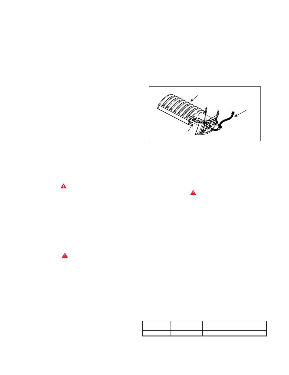
MAIN BURNER AND IGNITER
Check main burner (figure 7) at least every 6 months for proper
fl ame characteristics. The main burner should display the following
characteristics:
BURNER HEAD
ASSEMBLY
BURNER TUBE
ASSEMBLY
H.S.I.
ASSEMBLY
FIGURE 8. MAIN BURNER AND IGNITER ASSEMBLY
1. Provide complete combustion of gas.
2. Cause rapid ignition and carryover of fl ame across entire burner.
3. Give reasonably quiet operation during ignition, burning and extinction.
4. Cause no excessive lifting of fl ames from burner ports.
If preceding burner characteristics are not evident, check for accumulation
of lint or other foreign material that restricts or blocks the air openings
to the heater or burner.
WARNING
SOOT BUILD-UP INDICATES A PROBLEM THAT REQUIRES
CORRECTION BEFORE FURTHER USE. CONSULT WITH A
QUALIFIED SERVICE TECHNICIAN.
Should the main burner or burner air openings require cleaning, remove
the burner and clean with a soft brush. Clean main burner orifi ce with
a suitable soft material.
CHECK FOR GOOD FLOW OF COMBUSTION AND VENTILATING
AIR TO THE UNIT. MAINTAIN A CLEAR OPEN AREA AROUND THE
HEATER AT ALL TIMES. DO NOT STORE COMBUSTIBLES OR
FLAMMABLE LIQUIDS NEAR OR AROUND AN APPLIANCE.
CHECKING GAS INPUT
For appliance installation locations with elevation above 2000 ft.(610m)
refer to HIGH ALTITUDE INSTALLATIONS section of this manual for
input reduction procedure.
With this heater in operation, determine whether it is receiving the full
rated input of gas. This may be done by timing the gas meter and
measuring gas pressure with a gauge or manometer. When the heater is
operating at full capacity (full gas input) it should consume approximately
1 cubic foot of gas in the time shown in table 6.
TABLE
7
INPUT CHECK TIME REQUIRED TO CONSUME 1 CU. FT. OF GAS