Status light code, Water temperature adjustment, Operating modes and settings – State GS6 40 YBFS User Manual
Page 21
21
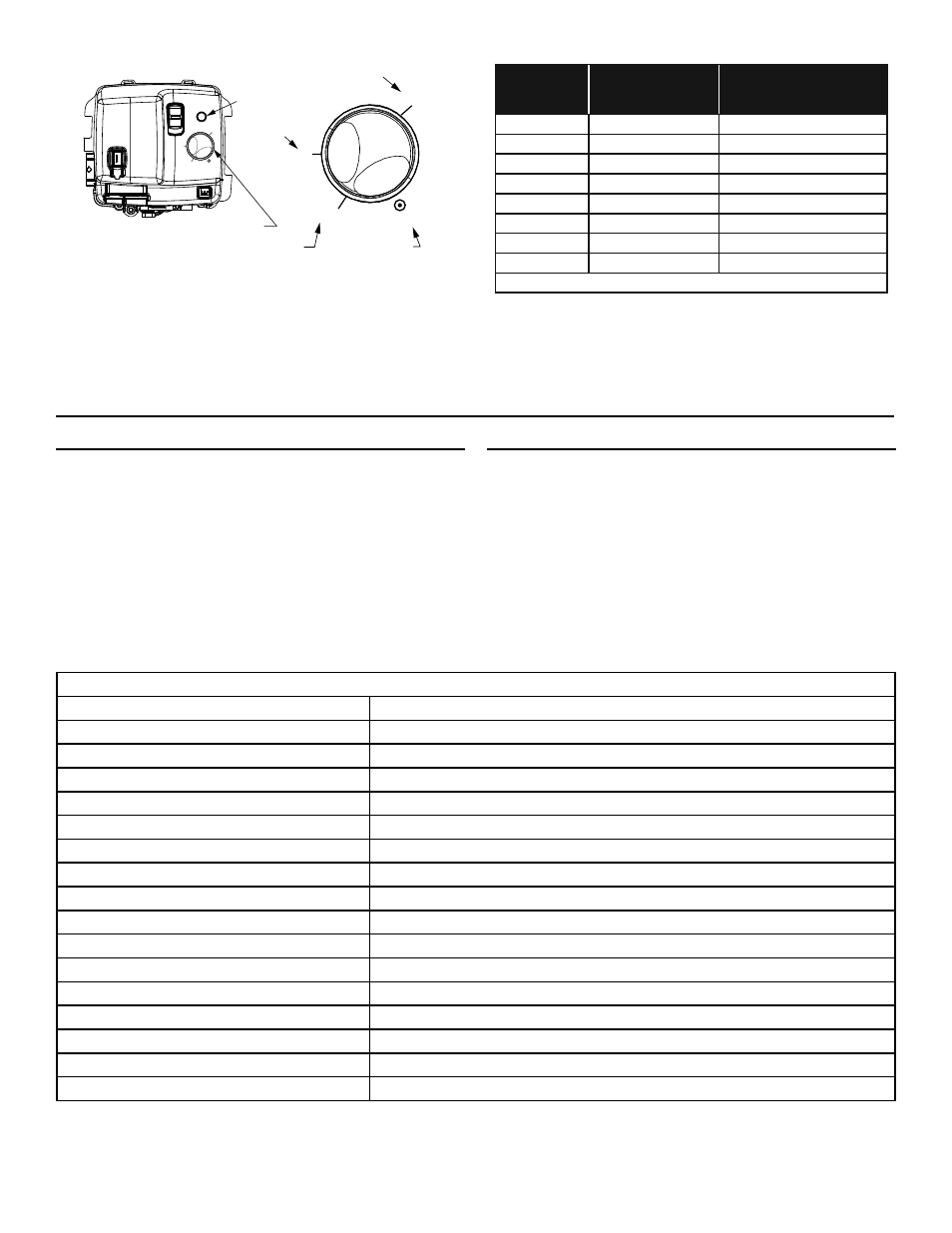
Gas Control/Temperature Knob
Status Light
ON
OFF
STATUS
120°F
Position
A
B
C
•
•
VE
RY
HOT
HOT
LOW
VAC
A
B
C
•
•
VER
Y
HOT
HOT
LOW
VAC
160°F (Approx.)
110°F (Approx.)
70°F (Approx.)
Water
Temperature
°F
Time for 1st
Degree Burn
(Less Severe Burns)
Time for Permanent Burns
2nd & 3rd Degree
(Most Severe Burns)
110
(normal shower temp.)
116
(pain threshold)
116
35 minutes
45 minutes
122
1 minute
5 minutes
131
5 seconds
25 seconds
140
2 seconds
5 seconds
149
1 second
2 seconds
154
instantaneous
1 second
(U.S. Government Memorandum, C.P.S.C., Peter L. Armstrong, Sept. 15,1978)
NOTE: During low demand periods when hot water is not
being used, a lower thermostat setting will reduce energy
losses and may satisfy your normal hot water needs. If hot
water use is expected to be more than normal, a higher
thermostat setting may be required to meet the increased
demand. When leaving your home for extended periods
(vacations, etc.) turn the temperature dial to its lowest
setting. This will maintain the water at low temperatures
with minimum energy losses and prevent the tank from
freezing during cold weather.
Water Temperature Adjustment
The water temperature setting can be adjusted from 70°F to
160°F. Turn the Gas Control/Temperature Knob to the desired
setting/temperature.
NOTE: The temperatures indicated are approximates. The actual
temperature of the heated water may vary.
Operating Modes and Settings
•
Standard Mode - The controller adjusts the water
heater to maintain the temperature set by the user.
• Vacation
Setting - The Vacation Setting (VAC) sets
the controller at approximately 70°F. This setting is
recommended when the water heater is not in use for a
long period of time. This effectively turns the controller
temperature setting down to a temperature that
prevents the water in the water heater from freezing
while still conserving energy.
Status Light Code
Table 5
LED FLASH SEQUENCE
CONTROL STATUS
Short flash once every four second
IDLE (No call for heat, no fault conditions)
“Heartbeat”, alternates bright/dim
Call for Heat (No fault conditions)
One Flash, three second pause
Low Flame Signal (control continues to operate)
Two Flash, three second pause
End Switch Failed Closed
Three Flash, three second pause
End Switch Failed Open or TCO Limit Lockout
Four Flash, three second pause
ECO Limit Lockout (Overheat Failure)
Five Flash, three second pause
Flame Out of Sequence
Six-One Flash, three second pause
Soft Lockout* - Retry Limit - Failed TFI (Trial for Ignition)
Six-Two Flash, three second pause
Soft Lockout* - Recycle Limit - Flame Lost - END Switch Fails
Six-Three Flash, three second pause
Soft Lockout* - Recycle Limit - Flame Lost
Six-Four Flash, three second pause
Soft Lockout* - Flame out of Sequence Sensed
Seven Flash, three second pause
Flammable Vapor Sensor (FVS) Lockout
Eight-One Flash, three second pause
Flammable Vapor Sensor (FVS) Fault Detected
Eight-Two Flash, three second pause
Temperature Sensor Fault Detected
Eight-Three Flash, three second pause
Electronic Fault Detected
Eight-Four Flash, three second pause
Gas Control Valve/Thermostat Fault Detected
* Soft Lockout - 20 minute wait before returning to normal mode.
FIGURE 22.