Tuff Country 24975 - Ford 08-14 F250/F350 5 box kit User Manual
Page 8
20. Repeat steps 18 and 19 on the passenger side of the
vehicle.
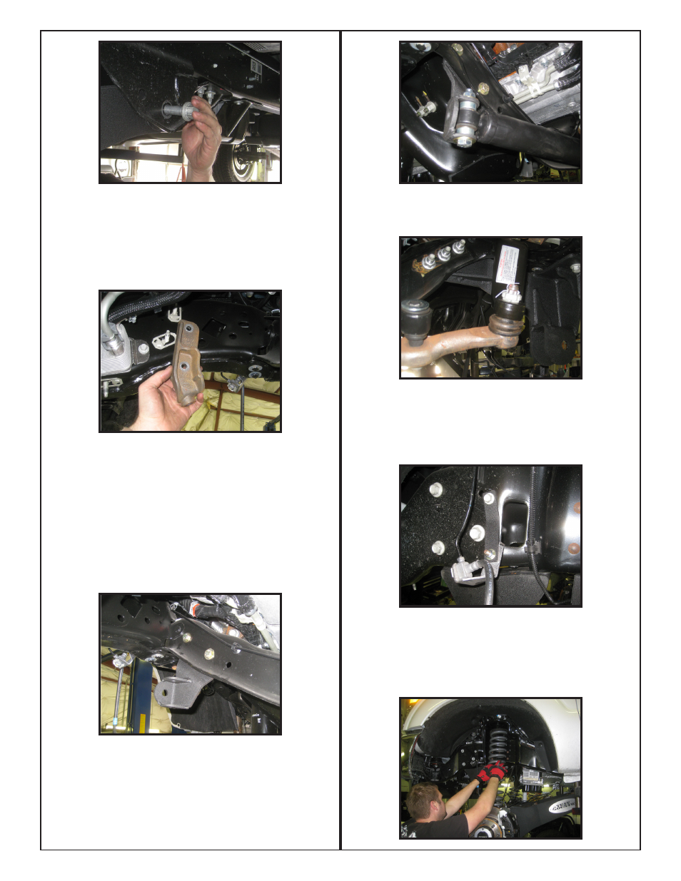
21.Locate and remove the OE steering stabilizer mount from
the frame rail. This bracket is located on the inside passen-
ger side frame near the sway bar mount.
22. Locate the new steering stabilizer bracket. Also locate
(2) 7/16” x 1 1/2” bolts, (4) 3/8” washers, (2) 7/16” uni-torque
nuts, (1) 12mm x 80mm bolt, (2) 12mm washers, (1) 12 mm
uni-torque nut, and (2) S10090 crush sleeves from hardware
bag 24975NB.
23. Install the new steering stabilizer bracket to the back side
of the engine crossmember using the 2 holes closest to the
passenger side frame rail. Secure the new bracket using the
new 7/16” hardware.
Torque bolts to 45 ft lbs.
24. Place the eyelet of the OE steering stabilizer into the
new bracket and secure using new 12mm hardware. Use
the S10090 crush sleeves to fill the gap on each side of the
eyelet.
torque to 45 ft lbs.
25. Re-connect the steering drag link end to the new pitman
arm using the OE Nut, nut retainer, and cotter pin.
torque
nut to 90 ft lbs.
26. Locate (2) Brake line brackets. Also locate (2) 5/16” x 1”
bolts, (4) 1/4” washers, and (2) 5/16” uni-torque nuts. Install
the brackets to the OE threaded holes on the frame using
the OE bolt, and connect the OE bracket to the bottom of the
newly installed bracket using the 5/16” hardware.
27. Locate new coil springs, and the OE rubber isolators
that were removed in step #6. Place the rubber isolator on
the top of the coil spring, lower the axle enough to install
new coil spring.
Take special care not to over extend any
brakelines or wiring when lowering the front axle.