Tuff Country 24975 - Ford 08-14 F250/F350 5 box kit User Manual
Page 3
Hardware bag 24975NB includes:
Description
Quantity
M30JN
30mm
jam
nut
1
716112B
7/16” x 1 1/2” bolt
6
38WA
3/8” USS flat washer
12
716UN
7/16”
unitorque
nut
6
M18UN
18mm
2.50
nut
1
M1280B
12mm x 80mm bolt
1
M12UN
12mm
unitorque
nut
1
M12WA
12mm flat washer
2
716212B
7/16” x 2 1/2” bolt
2
5161B
5/16”
x
1”
bolt
4
14WA
1/4” USS flat washer
8
516UN
5/16”
unitorque
nut
4
Special note: Before installation begins, it is the
customers/installers responsibility to make sure that
all parts are on hand. If any parts are missing, please
feel free to call one of our customer service represen-
tatives @ (801) 280-2777.
Recommended tools selection:
Torque wrench
Standard socket set
Standard wrench set
Metric socket set
Metric wrench set
Tape measure
Hydraulic floor jacks
Please follow instructions carefully:
Before installation begins, measure from the center of
the hub, to the bottom of the fender well, and record
measurements below.
Pre-installation measurements:
Driver side front:_______________________________
Passenger side front:___________________________
Driver side rear:________________________________
Passenger side rear:____________________________
At the end of the installation take the same measure-
ments and compare to the pre-installation measure-
ments.
Post installation measurements:
Driver side front:______________________________
Passenger side front:__________________________
Driver side rear:_______________________________
Passenger side rear:___________________________
Front end installation:
1. Safely block the rear tires of the vehicle so the vehicle is
stable and can not roll backwards. Using a pair of hydraulic
floor jacks, raise up on the front axle until the front tires
can be removed. Support the frame on each side using
jack stands
2. Working on the driver side, remove the brakeline brack-
et bolt from the frame rail, save bolt for later installation.
Repeat on passenger side.
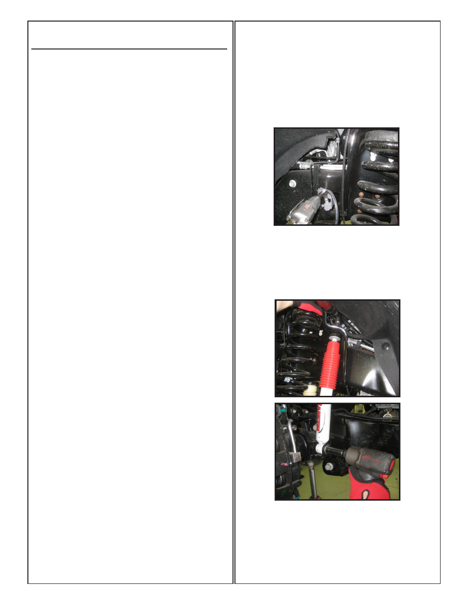
3. Working on the driver side, remove the nut, washer, and
rubber bushing from the top of the shock absorber. Repeat
on passenger side.
4. Now remove the bolt and nut from the bottom mounting
location of the front shock absorber, save hardware for
later installation. Remove shocks from the vehicle.
4. Working on the front swaybar, remove the 4 bolts holding
it to the bottom of the frame rails, and carefully let the sway
bar hang from its endlinks.