Installation (cont’d) – Powerwinch Class 46' User Manual
Page 6
Make sure all crimps/
connections can withstand
at least 25 pounds of pullout
force. Failure to make strong
enough crimps between wire
connectors and wires could
create a fire hazard.
1. Measure and cut 6-gauge red and
black wire to run from anchor winch to
relay. Allow some slack to prevent
connections being too short leaving
enough room to crimp end of wire.
Install wire in boat before crimping any
connections. Use cable ties to secure
wiring to boat.
2. When running wire from anchor winch
to relay, be sure to keep wire away
from sources of intense heat or areas
where insulation of wire could be worn
away. Cable ties can be used to secure
wiring to boat.
3. After wire is installed and secured,
connection to anchor winch can be
made.
4. Crimp 3/8” ring terminals to 6-gauge
red and black wire connected to anchor
winch.
5. Attach 6-gauge red wire to red wire
coming from anchor winch. Secure
junction by placing a 1/4”-20 x 1/2”
6
screw through ring terminals and tighten
a 1/4”-20 nut on screw. Protect junction
by placing a 1” diameter piece of heat
shrink tubing over connection and
applying heat until tubing is secure.
6. Attach 6-gauge black wire to black wire
coming from anchor winch. The junction
can be secured in same manner as 6-
gauge red wire in step 5.
7. The connections at relay from
anchor winch can now be made.
8. Crimp 3/8” female disconnects to red and
black wires to be attached to relay.
9. Connect 6-gauge red wire to relay
on post marked M1 and secure
by tightening supplied nut.
10. Connect 6-gauge black wire to relay
on post marked M2 and secure
by tightening supplied nut.
Make sure all crimps/
connections can withstand
at least 25 pounds of pullout
force. Failure to make strong
enough crimps between wire
connectors and wires could
create a fire hazard.
1. Measure a 16-gauge red, white,
and black wire to run from switch to
relay. Allow some slack to prevent
connections being too short leaving
enough room to crimp end of wire.
Install wire in boat before crimping any
connections. Use cable ties to secure
wiring to boat.
2. When running wire from switch to
relay, be sure to keep wire away
from sources of intense heat or areas
where insulation of wire could be worn
away. Cable ties can be used to secure
wiring to boat.
3. Once wires are run and secured,
connect wires from switch to relay.
4. Starting on the wire ends for switch,
crimp one 16-gauge insulated female
disconnect to red wire.
5. Plug red wire into middle post on back
of switch.
6. Next, crimp a 16-gauge insulated
female disconnect to white wire.
7. Plug white wire into top post on back of
switch.
8. Crimp a 16-gauge insulated female
disconnect to black wire.
9. Plug black wire into bottom post on
back of switch.
10. Make connections at relay.
11. Crimp a 16-gauge insulated female
disconnect to white wire.
12. Plug white wire into terminal marked
S1
on the relay.
13. Crimp a 16-gauge insulated female
disconnect to black wire.
14. Plug black wire into terminal marked
S2
on relay.
15. Using a 16-gauge butt connector,
connect fuse holder to red wire.
16. Crimp a 16-gauge insulated female disconnect
to remaining open end of fuse holder.
17. Attach fuse holder with disconnect
crimped to it to terminal marked
S3
on relay
.
18. Insert 10 amp ATO style fuse in fuse
holder.
Make sure all crimps/
connections can withstand
at least 25 pounds of pullout
force. Failure to make strong
enough crimps between wire
connectors and wires could create a fire
hazard.
1. Measure 6-gauge red and black wire
to run from relay to battery. Allow
Operating Instructions and Replacement Parts List
WIRING SWITCH TO RELAY
WIRING RELAY TO BATTERY
Installation (Cont’d)
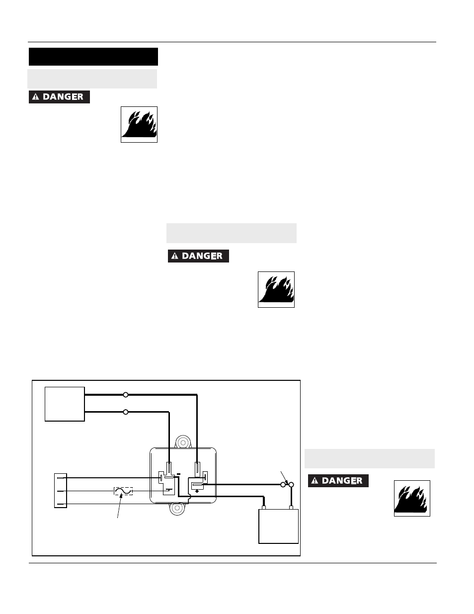
WIRING ANCHOR WINCH TO
RELAY (REFER TO FIGURE 6)
M1
M2
S2
S1
S3
Anchor
Winch
Black
(from motor)
Red
(from motor)
Black
6-Gauge
Red
6-Gauge
Control
Switch
UP
DWN
White
16-Gauge
Red
16-Gauge
Black
16-Gauge
10A Inline Fuse
Battery
Red
6-Gauge
Black
6-Gauge
Circuit Breaker
Relay
Module
PW46001