Installation (cont’d), Wiring installation – Powerwinch Class 46' User Manual
Page 2
Do not use electrical wire
sizes or types other than those
specified or included with this
product.
Use supplied or recommended
circuit breakers for safe
installation. The warranty will be
void and fire can result from using improper
circuit breakers.
2
MATERIAL REQUIRED (INCLUDED WITH
ANCHOR WINCH):
1. Three 5/16”-18 stainless steel threaded
rods. These rods secure anchor
winch to boat. Length is determined by
thickness of boat deck.
2. Three lock washers (5/16” stainless
steel)
3. Three plain washers (5/16” stainless
steel)
4. Three nuts (5/16”-18 stainless steel)
MATERIAL REQUIRED (NOT INCLUDED):
NOTE: A wiring kit from Powerwinch® (Part
No. P55800) is available which contains
items 2-13.
1. Marine plywood for under deck support
(optional)
2. Six 1/4”- 20 x 1/2” hex head stainless
steel screws
3. Six 1/4”- 20 x 1/2” stainless steel nuts
4. Ten 5/16” 8-gauge ring terminals
5. #12 AWG red wire class 105°C
6. #12 AWG black wire class 105°C
7. Four 5/16” 12-gauge ring terminals
8. #8 AWG black wire class 105°C
(6-gauge
40’)
9. #8 AWG red wire class 105°C (6-Gauge
40’)
10. 1” diameter heat shrink tubing
11. 2” diameter heat shrink tubing
12. Wire ties
13. Four 12-gauge insulated female
disconnects
14. Silicone sealer
15. Loctite® 242 thread locker (optional)
1. Place mounting template in desired
position on deck and secure with tape
into position. Ensure center-line of
gypsy lines up with centerline of davit
or bow roller.
IMPORTANT: Be certain anchor winch is
positioned above rope locker before drilling
any mounting holes. The anchor line and
chain will feed into rope locker through a
2
1
/
2
” hole in boat deck and a molded part
called the rode glide. Minimum rope locker
dimensions required for proper storage of
anchor lines are shown in Chart 1.
2. Using a punch, mark center of each
mounting hole to be drilled. Remove
template and drill holes with an electric
drill. There are three
11/32
” holes for
mounting studs, one 2
1
/
2
” hole for deck
insert, and one 5/8” hole for wiring
harness.
3. Place round side of insert into 2
1
/
2
”
hole and seat deck insert so lip is flush
with boat deck. The half circle portion
of deck insert must be pointing toward
bow of boat.
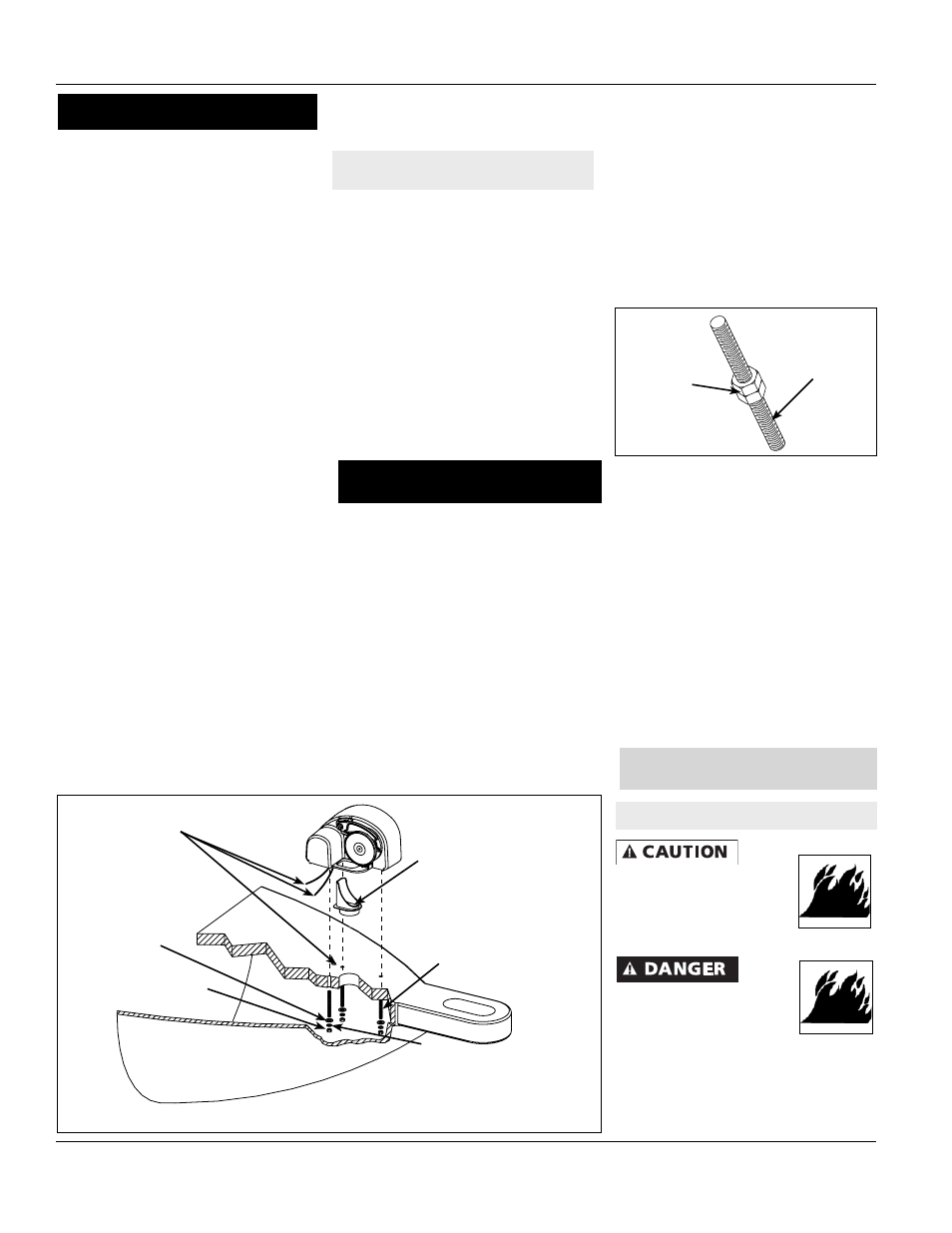
4. Insert three mounting studs into
threaded holes on underside of winch.
A small amount of thread locker can be
used to secure studs in housing. Use
two mounting nuts to help tighten studs
into housing as shown in Figure 2.
5. Gently guide winch over rode glide so
loop on anchor winch housing slides
over deck insert. Slide three mount-ing
studs into the three mounting holes
in deck. Feed wiring harness from
underside of winch through 5/8” hole.
6. The winch must fit squarely over deck
insert and onto deck. Slide flat washers
and lock washers onto mounting studs.
Tighten nuts to fully secure the winch to
the deck.
7. Examine winch to make sure unit is
securely fastened and that centerline of
gypsy is aligned with centerline of bow
roller or davit.
Installation (Cont’d)
Line Locker
Dimensions Dimensions (L x W)
1/2” x 200’ 15” x 17”
1/2” x 300’ 15” x 24”
5/8” x 200’ 15” x 24”
5/8” x 300’ 16” x 32”
Chart 1
Figure 1 - AW31’, 36’, 41’ Class
Figure 2
Mounting Stud
Mounting
Nuts
Operating Instructions and Replacement Parts List
5/8” Hole in Deck for
Motor Lead Wires
Rode Glide
Lock Washer
Flat Washer
Hex Nut
Stud
MOUNTING ANCHOR WINCH ONTO
DECK
WIRING AND SWITCH INSTALLATION
Wiring Installation
NOTE: Mounting and gasket hardware
available in kits (P/N P10349 & P11162).
See page 11 for ordering information