Installation (cont’d) – Powerwinch Class 46' User Manual
Page 5
10. Two 1/4”-20 x 1/2” stainless steel nuts
11. 1” diameter heat shrink tubing
12. 2” diameter heat shrink tubing
13. ATO inline fuse holder
14. 10A ATO style fuse
15. Wire ties
16. Loctite® 242 thread locker (optional)
17. Silicone sealer
1. Place mounting template in desired
position on deck and secure with tape
into position. Ensure center-line of
gypsy lines up with centerline of davit
or bow roller.
IMPORTANT: Be certain anchor winch
is positioned above rope locker before
drilling any mounting holes. The anchor
line and chain will feed into rope locker
through a 2
1
/
2
” hole in boat deck and a
molded part called deck insert. Minimum
rope locker dimensions required for
proper storage of anchor lines are shown
in Chart 2.
2. Spot holes with center punch as
shown on template. Use an electric
drill to drill holes. There are three
11/
32
” holes for mounting studs, one 2
1
/
2
” hole for deck insert, and one 5/8”
hole for wiring harness.
3. Place round side of insert into 2
1
/
2
” hole
and seat deck insert so lip is flush with
boat deck. The half circle portion of
deck insert must be pointing toward
bow of boat.
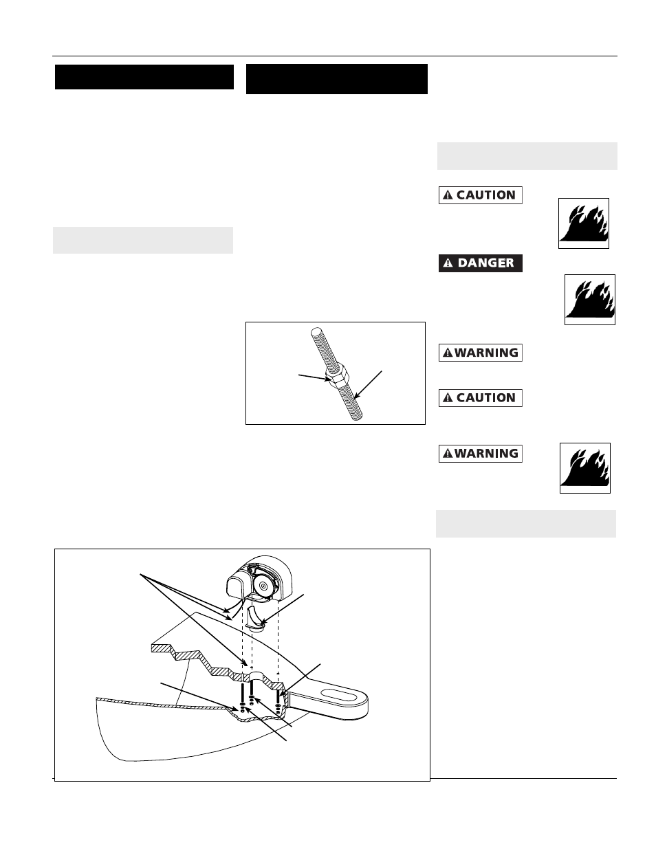
4. Insert three mounting studs into
threaded holes on underside of winch.
A small amount of thread locker can
be used to secure studs in housing.
Use two mounting nuts to help tighten
studs into housing as shown in Figure
5.
5. Gently guide winch over rode glide
so loop on anchor winch housing
slides over deck insert. Slide three
mounting studs into three mounting
holes in deck. Feed wiring harness
from underside of winch through 5/8”
hole.
6. The winch must fit squarely over
deck insert and onto deck. Slide
flat washers and lock washers onto
mounting studs. Tighten nuts to fully
secure winch to deck.
8. Examine winch to make sure unit is
securely fastened and that center-line
of gypsy is aligned with centerline of
bow roller or davit.
Do not use electrical wire
sizes or types other than
those specified or included
with this product.
Use supplied or recommended
circuit breakers for safe
installation. The warranty will
be void and fire could result
from using improper circuit
breakers.
Always disconnect
wiring harness from
battery before attempting to install, service
or relocate unit.
Follow order of
wiring steps to
ensure power is not applied to anchor
winch until all wires and circuit breakers
are installed.
Always keep wires away
from intense sources of heat.
Be sure newly installed wires
are away from any exposed bare wires.
1. Select a suitable location (console,
etc.) to locate switch. Make sure
there is enough room behind switch
mounting surface for entire switch
and wires.
2. Cut a hole 1
3
/
4
” high and 1” wide.
3. Apply a thin band of silicone sealer
around edge of switch mounting plate
and attach plate using four #8 round
head wood screws.
4. Select a suitable location for relay
(reversing switch). Locate reversing
switch within 6-8 feet of switch plate
and in a location away from exposure
to water. Mount relay with power
terminals facing up.
5
31’, 36’, 41’, 46’ Class Anchor Winch
LOCATING MOUNTING HOLES FOR
ANCHOR WINCH
WIRING AND SWITCH INSTALLATION
Installation (Cont’d)
Figure 4 - AW46’ Class
5/8” Hole in Deck for
Motor Lead Wires
Rode Glide
Lock Washer
Flat Washer
Hex Nut
Stud
NOTE: Mounting and gasket hardware
available in kits (P/N P10349 & P11162)
Line Locker
Dimensions Dimensions (L x W)
1/2” x 200’ 15” x 17”
1/2” x 300’ 15” x 24”
5/8” x 200’ 15” x 24”
5/8” x 300’ 16” x 32”
Chart 2
Figure 5
Mounting Stud
Mounting
Nuts
SWITCH AND SOLENOID LOCATION
18. four 3/8” 6-gauge female disconnects