Installation (cont’d) – Powerwinch Class 46' User Manual
Page 3
3
terminals together. Protect junction
by placing a 1” diameter piece of
heat shrink tubing over connection
and applying heat until the tubing is
secure.
SWITCH TO ANCHOR WINCH
The switch needs 12-gauge wire
connections and wiring just run is 8-
gauge. To complete anchor winch
to switch connections construct two
conversion wires by following these steps:
1. This switch wire is for the positive
(red) lead.
2. Cut a 1 foot section of 12-gauge red
wire and crimp a 5/16” ring terminal to
one end.
3. Crimp an insulated female disconnect
to other end.
4. Crimp a 5/16” ring terminal to 8-
gauge red wire coming from anchor
winch.
5. Using a 1/4”-20 x 1/2” screw, connect
8-gauge red wire coming from anchor
winch to ring terminal on red switch
wire. Tighten a 1/4”-20 nut to secure
ring terminals together. Protect
junction by placing a 1” diameter piece
of heat shrink tubing over connection
and applying heat until tubing is
secure.
6. Plug insulated female disconnect on
end of red switch wire to rocker switch
on terminal marked “A”.
7. To construct second switch wire and
make connection to switch, cut a 1
foot section of 12-gauge black wire
and crimp a 5/16” ring terminal to one
end.
8. Crimp an insulated female disconnect
to other end.
9. Crimp a 5/16” ring terminal to 8- gauge
black wire coming from anchor winch.
10. Using a 1/4”-20 x 1/2” screw, connect
8-gauge black wire coming from anchor
winch to ring terminal on black switch
wire. Tighten a 1/4”-20 nut to secure
ring terminals together. Protect junction
by placing a 1” diameter piece of heat
shrink tubing over connection and
applying heat until tubing is secure.
11. Plug insulated female disconnect on end
of black switch wire to rocker switch on
terminal marked “B”.
Always disconnect
wiring harness from
battery before attempting to install, service or
relocate unit.
Follow order of
wiring steps to ensure
power is not applied to anchor winch until all
wires and circuit breakers are installed.
Always keep wires away
from intense sources
of heat. Be sure newly
installed wires are away from any exposed
bare wires.
Make sure all crimps/
connections can withstand
at least 25 pounds of pullout
force. Failure to make strong enough crimps
between wire connectors and wires could
create a fire hazard.
1. Select a suitable location (console,
etc.) to locate switch. Make sure
there is enough room behind switch
mounting surface for entire switch and
wires.
2. Cut a hole 1
3/4” high and 1” wide.
3. Apply a thin bead of silicone sealer
around edge of switch mounting plate
and attach plate using four #8 round
head wood screws.
4. Measure and cut 8-gauge red and
black wire to run from anchor winch to
switch. Allow some slack to prevent
connections from being too short and
so connections can be crimped to
end of wire. Install wire in boat before
crimping any connections. Cable ties
can be used to secure wiring to boat.
5. When running wire from anchor winch
to switch, be sure to keep wire away
from sources of intense heat or areas
where the insulation of wire could be
worn away.
6. After wire is installed and secured,
connection to anchor winch can be
made.
7. Crimp a 5/16” ring terminal to 8-gauge
red wire just cut.
8. Using a 1/4”-20 x 1/2” screw, connect
8-gauge red wire to ring terminal on
the green wire coming from anchor
winch. Tighten a
1/4”-20 nut to secure ring terminals
together. Protect junction by placing a
1” diameter piece of heat shrink tubing
over connection and applying heat
until tubing is secure.
9. Crimp a 5/16” ring terminal to 8-gauge
black wire just cut.
10. Using a 1/4”-20 x 1/2” screw, connect
8-gauge black wire to ring terminal on
black wire coming from anchor winch.
Tighten a 1/4”-20 nut to secure ring
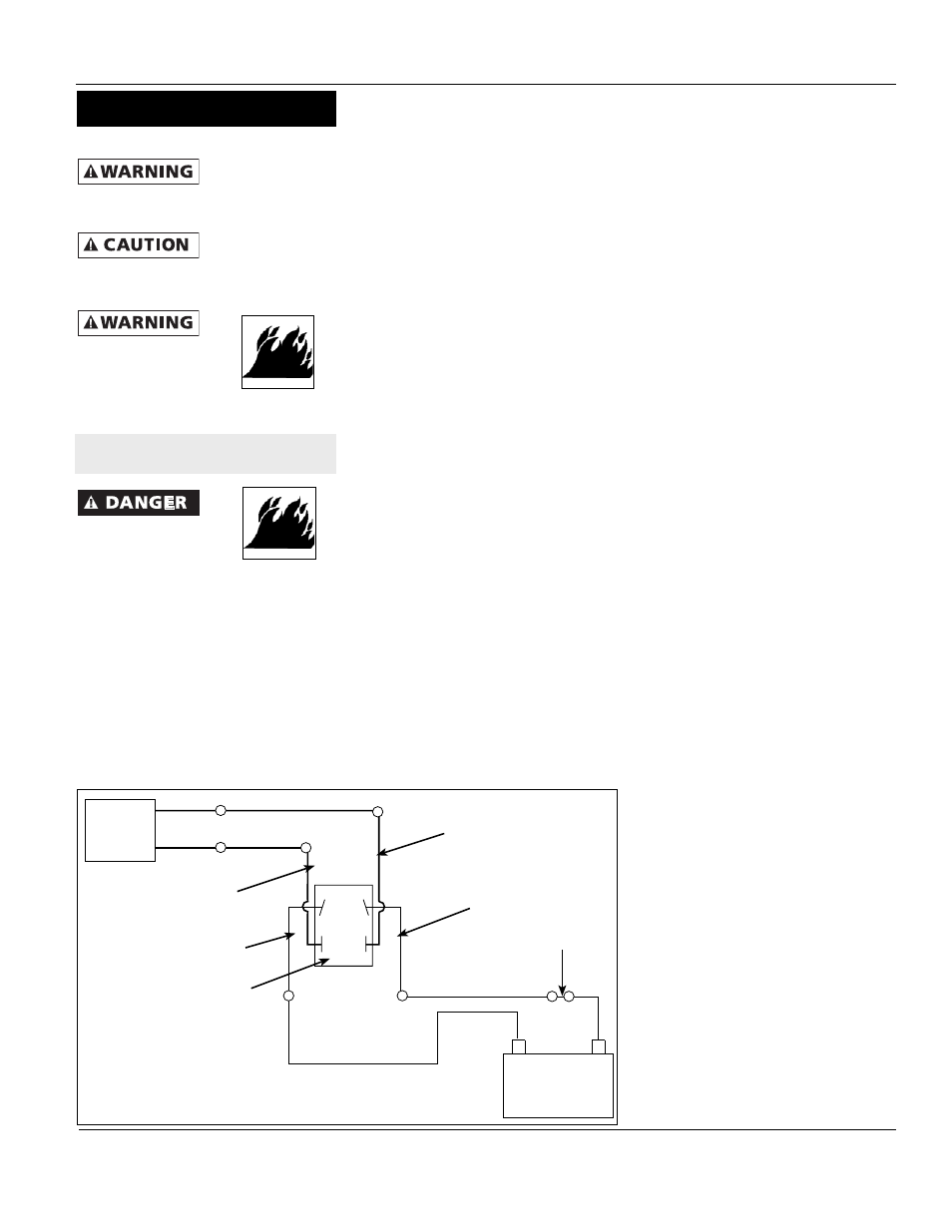
31’, 36’, 41’, 46’ Class Anchor Winch
+
-
A
B
C
D
Figure 3 - Wiring Diagram for 31’, 36’, 41’ Anchor Winch
Anchor
Winch
Black
Wire
Green
Wire
*8-Gauge Black Wire
*8-Gauge
Red Wire
12-Gauge
Red Wire
12-Gauge
Black Wire
Control Switch
(Back View)
*8-Gauge Black Wire
Battery
*8-Gauge Red Wire
Circuit
Breaker
12-Gauge
Red Wire
12-Gauge
Black Wire
*NOTE: 41’ Class uses
6-gauge red & black wire
SWITCH INSTALLATION
Installation (Cont’d)