Mc Leod 1300 Series Bolt On Hydraulic Bearing User Manual
Page 2
2
McLeod Bolt-On Hydraulic Throw Bearing Installation
Before installing the hydraulic throw out Bearing Assembly let’s take a look at your master
cylinder and pedal assembly combination. Key parts to the system:
1) Master cylinder bore size (3/4” recommended). Bore Diameter found on side of most
aftermarket master cylinders.
2) Clutch pedal travel.
3) Master cylinder “Push Rod” stroke should be 1”minimum.
4) 6:1 Pedal ratio. S
for more info.
The master cylinder push rod needs a minimum of 1” of stroke if using a ¾” bore master cylinder.
Less travel is required with a larger diameter bore, although pedal effort will increase. More travel is
required with a smaller diameter bore, with decrease in pedal effort. If a larger than ¾” bore is required
for your application, you can ease pedal effort by mounting the master cylinder and push rod higher up
the pedal toward the pivot point. This will increase the amount of leverage you have with the pedal, thus
an easier push. You will lose some push rod travel by doing this however with the larger bore master
cylinder you are dispensing more fluid per stroke to compensate for the loss of pedal travel.
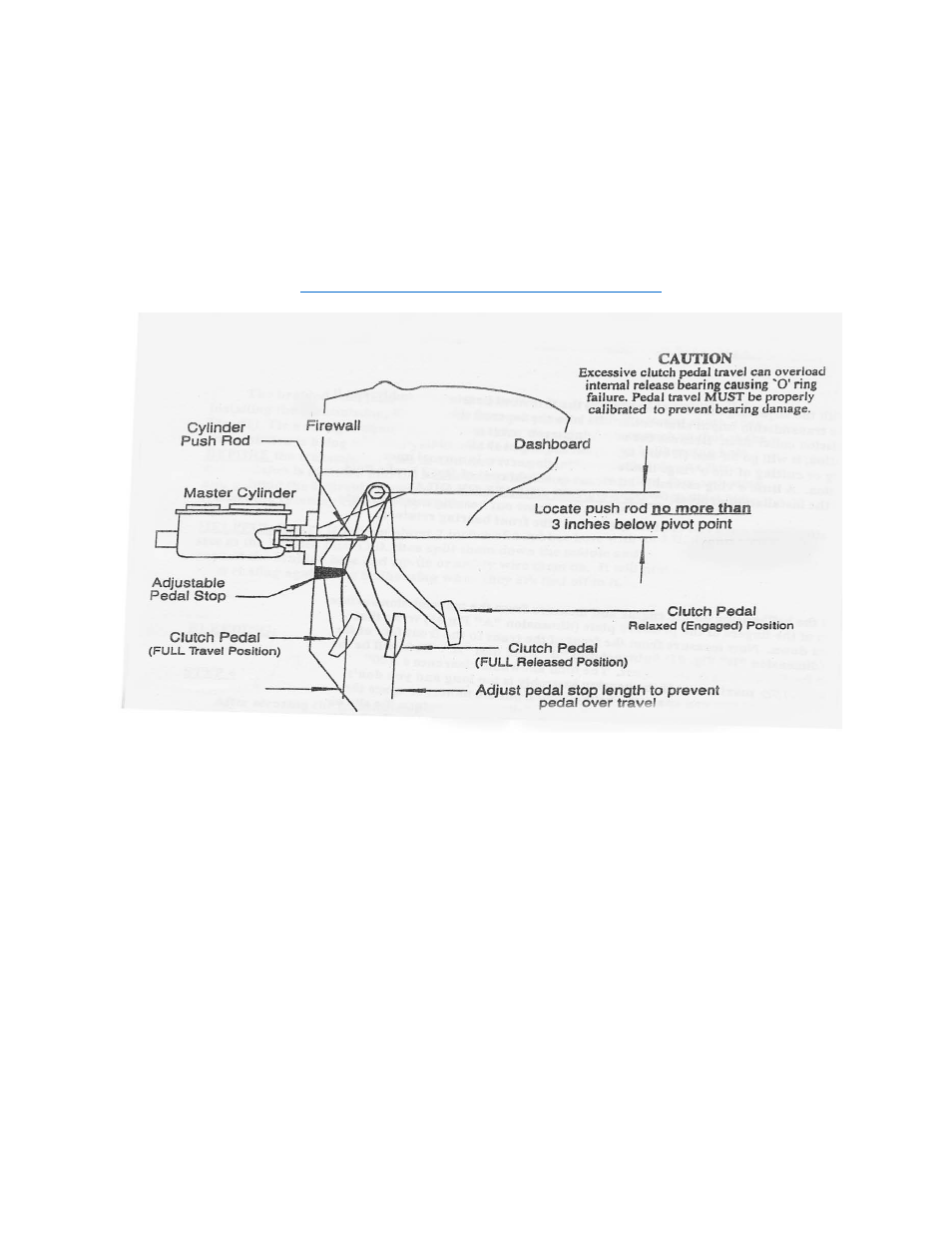
A 6 to 1 ratio is recommended with a ¾” bore master cylinder. Example…If the center of the pedal
pad is 12” from the pivot point, the push rod connecting point should be 2” below the pivot point. Quick
math: Pedal pad is 12” below pivot point, divided by 6 (desired ratio) = 2”. Push rod should be attached
to the pedal assembly 2” from the pivot point.
An optional pedal stop may be attached to the pedal or the firewall. A bracket with a bolt and a
jam nut work nicely so that the stop is adjustable for more or less travel. The pedal should stop just prior
to the piston, on the end of the cylinder push rod, contacting the front of the master cylinder.