The front panel – Manley BACKBONE Mastering Insert Switcher 2003 - present User Manual
Page 5
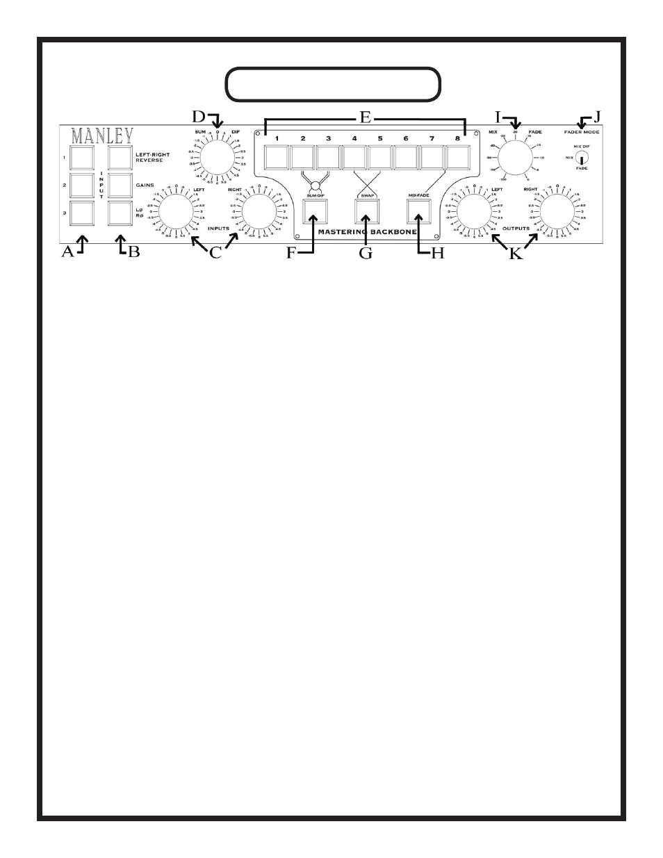
THE FRONT PANEL
A. INPUT 1, 2, 3: Choose which of the three inputs will drive the BACKBONE audio chain. Whichever
source is selcted here will also come out of the “SELECTED INPUT” XLRs on the back panel.
B. LEFT-RIGHT REVERSE: Allows you to swap left and right channels.
GAINS:
When lit, engages all active electronics for the input and output gains.
LØ RØ (polarity reverse): Changes the absolute polarity of the signal on both channels. For more on
this, see page 6.
C. INPUTS: Input signal level for each channel can be selected on these 24-position, 1/2 dB stepped con-
trols. Range is from +6 to -5.5 dB.
D. SUM-DIF Rotary Switch: Alters the level of the DIFFERENCE signal sent to Inserts 2 and 3. Acti-
vated only when the SUM-DIF button (F in this diagram) is engaged. For more info, see pages 7 & 13.
E. Inserts 1-8: Push to activate the outboard processor that is patched into that insert point. See page 7-8
for details.
F. SUM-DIF: Press to engage SUM-DIF circuit for processing of Inserts 2 & 3.
G. SWAP: Swaps the order of Inserts 4 & 5 so that Insert 5 comes before Insert 4 when engaged (illumi-
nated). See pages 8 and 13 for info and suggestions.
H. MIX-FADE Button: Activates the MIX-FADE knob (I in this diagram).
I. MIX-FADE Knob: Acts as a master fader or mixer, depending on the position of the FADER MODE
SWITCH (J in this diagram). For a detailed explanation, see pages 8 and 15.
J. FADER MODE Switch: This is a 3-position switch (I in this diagram) that determines the operating
mode of the MIX-FADE knob. The three modes are MIX DIF, MIX, and FADE. See pages 8 and 15
for more info.
K. OUTPUTS: Output signal level for each channel can be selected on these 24-position, ½ dB stepped
controls. Range is from +6 to -5.5 dB.
5