Block diagram – Manley The WAVE DAC/Preamp 24/96 Version Serial Code WAVE016-present 2002 - present User Manual
Page 19
19
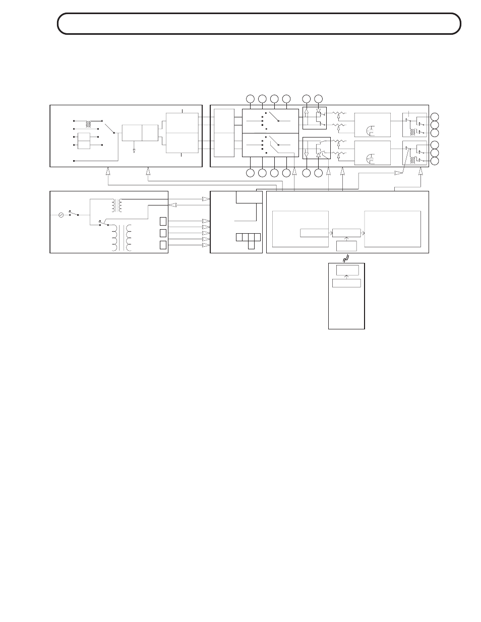
This is a rough block diagram of the WAVE with a little liberty taken for the sake of clarity.
The INPUT selection is done by a bunch of discrete relays. The careful board layout and
minimisation of close proximity wiring yields lower crosstalk figures over a conventional
rotary switch arrangement, for example. Also this switching buss is fully balanced so both
halves of the signal are switched.
The INSERT block shows the operational amplifiers needed to convert balanced signals to
unblanaced ones when the insert send and returns use unbalanced RCA connectors. The
balanced option eliminates those opamps because the buss is balanced and additional
buffering is not expressly needed for short balanced cable runs.
The circles represent input and output jacks and don't detail if they are balanced and
unbalanced lines. The Mute Switch shorts the output to ground in order to kill the signal.
Outputs 2 & 3 also short to ground for silence when they are off.
The 4 deck motorized volume pot is shown on the Analog Block above but in real life it
lives on its own little board behind the big knob along with the motor driver.
Except for the main cable between the Power Supply and the Analog Board, no attempt
was made to show power supply lines, however the location of some of the important
regulators is shown. There are three more 5V regs and two 15v regs on the DAC board
which are fed pre-regulated from the power supply.
FUSE PWR
STANDBY
BLOCK DIAGRAM
BLOCK DIAGRAM
BLOCK DIAGRAM
BLOCK DIAGRAM
BLOCK DIAGRAM
RLY
+5
R
-18
L
-18
R
+18
L
+18
POWER SUPPLY
A3
A2
A1
FILTER
ALIAS
ANTI-
PASSIVE
FILTER
ALIAS
ANTI-
PASSIVE
CONVERTER
CONVERTER
REGULATORS
DAC 5V
DAC 15V
ANALOG BOARD
LEDS & RELAYS
WARM-UP
TUBE 12V
TUBE 300V
STANDBY
LOGIC
REMOTE
TRANSMIT
IR
ADDRESS DIP
FRONT PANEL BOARD
RELAY DRIVE
LEDS
LOGIC
RECEIVER
IR
ADDRESS DIP
ADDRESS DIP
PANEL BUTTONS
INSERT
A4
A1
A2
A3
A4
ANALOG BOARD
MUTE
INSERT
LINE AMP
VACUUM TUBE
LINE AMP
VACUUM TUBE
OUT 1
OUT 2
OUT 3
OUT 3
OUT 2
OUT 1
OUTPUT
DIGITAL
ST
DIGITAL BOARD
RATE LEDS
SAMPLE
PHASE
SRC
DECODING
TOSLINK
S/PDIF
AES/EBU
Dig. Filter
PHASE