Dip switches – Manley The WAVE DAC/Preamp 24/96 Version Serial Code WAVE016-present 2002 - present User Manual
Page 13
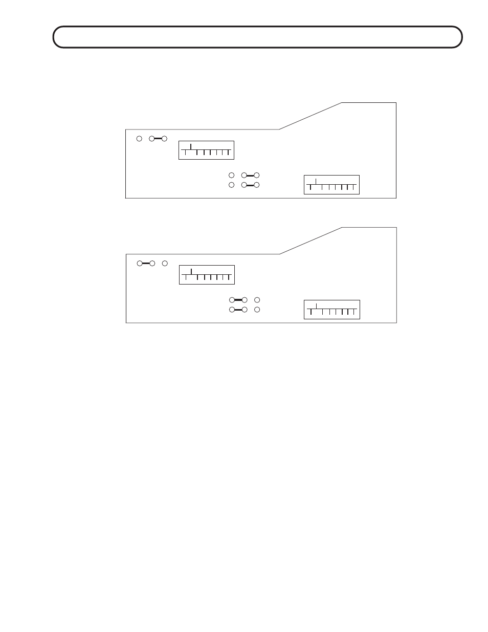
Jumpers marked P-04, P-05, P-06 are used to change from the default mode where OUT 2 and OUT
3 alternate interlocked or are individually (push on, push off) controlled. To set OUT 2 and OUT 3
to individually (push on, push off) mode refer to drawing for jumper configuration.
There are 3 sets of 8way dip switches, 2 on the Wave logic board marked SW-015 and SW-016 and
one in the remote. All 3 sets must be set identically for proper operation. These are used to set the
"address" function of the remote control, IR receiver and front panel. They should only be changed
in the unlikely scenario where one of your other remote controls and the Wave clash. They allow the
Wave to use a different remote control "address". All 3 should be set the same unless for some
reason you want the front panel buttons disabled. In that case, change SW-015 to be unique.
REAR VIEW
BACK OF FRONT PANEL
DIP SWITCHES
DEFAULT MODE
P-04,P-05,P-06
"FACTORY DEFAULT"
OUT 2,OUT 3 ALTERNATE
SW-015
SW-016
1
2
3
1
2
3
1
2
3
P-06 BLACK
P-04 RED
P-05 BLUE
"DRAWING NOT TO SCALE"
DIP SWITCHES
DEFAULT MODE
P-04,P-05,P-06
OUT 2, OUT 3
INDIVIDUALLY
CONTROLLED
SW-015
SW-016
1
2
3
1
2
3
1
2
3
P-06 BLACK
P-04 RED
P-05 BLUE
dip switches
dip switches
dip switches
dip switches
dip switches
13
*See notes below