Rear panel – Manley VOXBOX - MVB 1996 - 2/2000 and MVBX 6/2000 - 4/2003 User Manual
Page 7
7
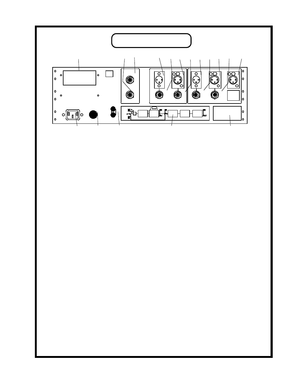
REAR PANEL
A B C D E
Q P O N M L K J I H G F
A
IEC POWER CONNECTOR: Use the IEC detachable power cable that was packed with the VOXBOX.
The correct mains voltage is factory wired for your country. The third pin ground is connected to the
chassis internally.
B
MAINS FUSE: Replace only with the same value and type which is 1 AMP SLO BLO. A generic type
is MDL 1 and its size is 1 1/4" X 1/4". A second or third blown fuse may indicate an electronic problem
needing repair especially if it has turned black. If it appears to be a serious problem, you should send the
VOXBOX to your dealer or to MANLEY LABS for repair.
C
GROUND TERMINALS: These are used to find or fix hum or to prevent ground loops with a variety
of studio wiring techniques. The CIRCUIT GROUND may be also called audio ground or "technical
earth" and it simply is the common ground of the audio circuits in this unit. The CHASSIS GROUND
is the third pin mains ground and the chassis. Separating CHASSIS GROUND and CIRCUIT GROUND
is the same as breaking off the third pin of the AC plug except that it includes the chassis which is also
probably grounded to the rack. These two terminals are normally joined by a small piece of metal called
a ground strap. If you loosen the posts you can move the strap to the side - you can also lose the strap
if you don't re-tighten the posts. For some studio grounding techniques the AUDIO GROUND can be
connected to the console with a piece of wire. If you have a hum, experiment here first.
D
BLOCK DIAGRAM: Shows a simplified drawing that shows the basic signal flow. This diagram is also
on page 10 in this manual.
E
CONNECTOR PIN-OUT: A list of how the XLR and phone jacks are wired that might help the person
building the cables. This info is also in detail below.
F
MIC INPUT: The mic cable gets plugged in here. 48 volt Phantom Power is available on this connector
(see page 5). The input impedance is 2400 ohms and is matched for most professional mics. The PIN-
OUT of all the XLRs is as follows: PIN 1 = CIRCUIT GROUND = SHIELD
PIN 2 = HOT = positive going signal +
PIN 3 = LOW = negative going signal -
G
LINE INPUT. For balanced or unbalanced +4 line level sources. Transformer coupled 1/4 inch phone
jack. The PIN-OUT is :
BALANCED - (using a stereo phone plug ) UNBALANCED - (using a mono or stereo plug)
TIP = HOT = positive +
TIP = SIGNAL = HOT
RING = LOW = negative -
(RING = GROUND = SHIELD)
SLEEVE = GROUND = SHIELD
SLEEVE = GROUND = SHIELD
MIC INPUT
LINE INPUT
INSERT INPUT
COMPRESSOR
DE-ESSER
PREAMP OUT
EQ OUT
UNBALANCED
UNBALANCED
+ 4 dBm
+ 4 dBm
CIRCUIT
CHASSIS
GROUND
POWER
FUSE
REPLACE ONLY WITH
SAME TYPE AND VALUE:
1 AMP SLO-BLO
STEREO LINK
STEREO LINK
THIS SPACE FOR SERIAL NUMBER
DE-ESSER
LIMITER
PASSIVE EQ
PULTEC STYLE
BLOCK DIAGRAM
GAIN
SWITCH
BALANCED
OUTPUT
BALANCED
OUTPUT
UNBALANCED
OUTPUT
TUBE CIRCUIT
LINE AMPLIFIER
PASSIVE OPTO
EQUALIZER
INSERT
INPUT
UNBALANCED
OUTPUT
OUR 40 dB
TUBE PREAMP
MIC PRE
INPUT
LEVEL
COMPRESSOR
PHASE
INST IN
MIC IN
LINE IN
XLR PINOUT: ALL TRANSFORMER BALANCED
PIN 1 = SHIELD = GROUND
PIN 2 = HOT = POSITIVE PHASE
PIN 3 = LOW = NEGATIVE PHASE
1/4 PHONE INPUTS : BALANCED OR UNBALANCED
SLEEVE = SHIELD = GROUND
TIP = HOT = SIGNAL POSITIVE
RING = LOW = NEGATIVE OR GROUND
1/4 PHONE OUTPUTS : UNBALANCED ONLY
SLEEVE = SHIELD = GROUND
TIP = HOT = SIGNAL POSITIVE
BYPASSES TRANSFORMER / DISABLES XLR OUT
HANDCRAFTED IN USA
MANLEY LABORATORIES
13880 MAGNOLIA AVE., CHINO, CA 91710
PHONE (909) 627-4256 FAX (909) 628-2482
email: [email protected]
CE
TO PROTECT SPEAKERS:
BEFORE PATCHING
MICROPHONE:
VERIFY MONITORS
ARE TURNED DOWN.
BEST TO TURN OFF
PHANTOM POWER.
PASSIVE
OPTO CIRCUIT
CAUTION: RISK OF ELECTRIC SHOCK. DO NOT OPEN.
REFER ALL SERVICING TO QUALIFIED PERSONNEL ONLY.
WARNING: TO REDUCE THE RISK OF FIRE OR ELECTRIC SHOCK.
DO NOT EXPOSE THIS UNIT TO RAIN OR MOISTURE
LEAVE ROOM FOR VENTILATION WHEN MOUNTING