Tube & trim locations 18 – Manley VOXBOX - MVB 1996 - 2/2000 and MVBX 6/2000 - 4/2003 User Manual
Page 18
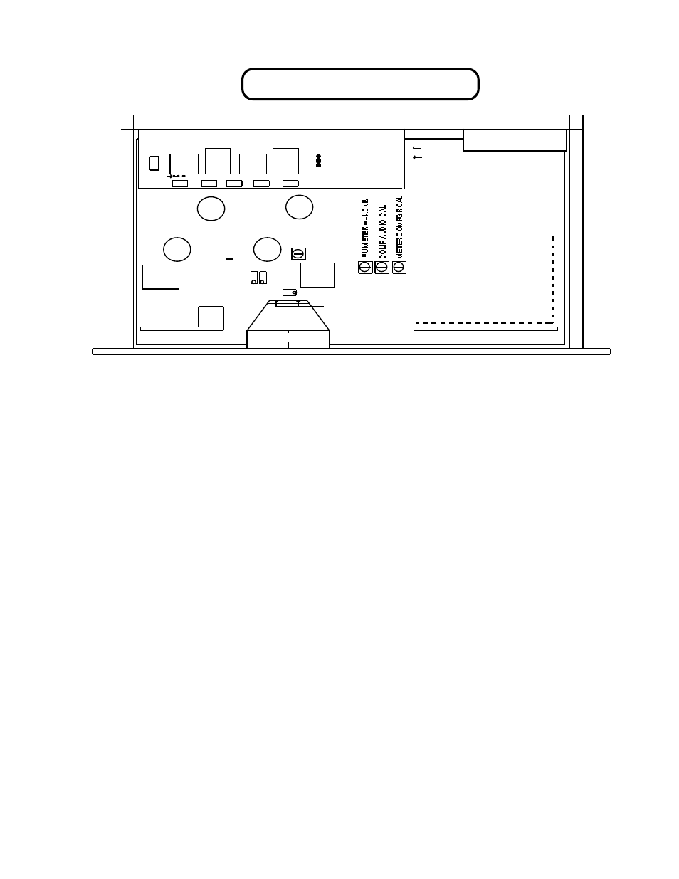
TUBE & TRIM LOCATIONS
18
TUBES: We use 4 tubes in the VOXBOX. All are 4 digit military spec JAN (joint army navy) types. The
substitutions listed just might work in a pinch but may not give optimum performance. Get
selected Mil Spec tubes from Manley Labs. A tube that does not glow or has turned white inside
needs to be replaced. A tube that makes too much audio noise when tapped (microphonic) or is
causing increased hiss should be replaced. The life of these tubes averages more than 5 years but
individual tubes cannot be predicted and may work 3 weeks or 30 years. Let the tubes cool before
handling to prevent burns. The list is:
6072A or 12AX7LPS
MIC PRE GAIN STAGE, very low noise tube, a good quiet 6072,
12AX7WA or ECC83 may work but expect more noise & microphonics and uncalibrated gain.
5751
EQ GAIN STAGE, better 12AU7WA or ECC82 may work OK
6414
LINE DRIVER, high current, 12BH7A may work OK but are hard to find now, 12AT7A
is the next best choice but does not have as much "poke".
TRIMS: Each VOXBOX has been factory calibrated and tested at least four times. These trims should not
be re-adjusted unless absolutely needed and should only be done by a qualified technician. The
function of each trim is labeled on the diagram above each trimmer and the order is below. The
complete procedure is on page 19. The technician will need these pages.
JUMPERS:
XLR PIN 1 grounds - Intended for some problem installations or special ground schemes.
Factory wired for PIN 1 = circuit ground. This can be changed with a soldering iron to be PIN 1
= chassis ground. Change the jumper from A to B now to B to C. This has little effect unless the
back panel ground strap is not connecting chassis and circuit ground.
LINE INPUT MODE - This is meant for some of our "purist" customers who want to achieve a
transformerless line path at the cost of losing one balanced line input (serial #020 or higher).
Factory wired for transformer balanced from both XLR and 1/4" jacks. Changing the "L TRANS
BYP" jumper makes both these unbalanced and transformerless. Change jumper D to E now to
E to F. A small wire is needed to connect from holes G & H to connect XLR pins 1 & 3 for
unbalanced. The signal is referenced to ground.
DIP SWITCHES: D1 if on, bypasses the turn-on delay. May be desired for live gigs or mobile recording.
D2 if on, shortens the turn on delay. If the unbalanced outputs are not used, then this setting will
be OK. There is only a small and "quick" thump that gets through the transformers to XLRs.
6414
METER DS GR CAL
EQ = UNITY GAIN
2
4
METER GR ZERO SET
METER LAMP = 12 VOLT, 100
mA, .91" X .25",
(remove 2 small phillips screws
on meter back to access)
LINE
IN
INSERT
IN
PRE
OUT
EQ
OUT
POWER
TRANSFORMER
12V FILAMENT
REGULATOR
2) 300V B+
REGULATOR
2) MULTICAP
OP COUPLING
+15V & -15V
REGULATORS
MIC
IN
EQ CAPS AND
INDUCTORS
3
1
6414
6072A
5
7
6
EQ IN SELECT & MUTING
POWER ON?OFF MUTE
E
M
M
E
E
L
CHASSIS GND
XLR PIN 1
CIRCUIT GND
GND
OPTOS
OPTO
DS / LIM
CAL
5751
F
E
D
LINE IN
TRANS
BYPASS