Gauge connection, Limited warranty and service procedures – Equus 8457 - 2-5/8 Vacuum/Boost Gauge User Manual
Page 2
© 2004 IEC - All Rights Reserved
GAUGE CONNECTION
4
Install Vacuum/Boost gauge as described in Section 2, MOUNTING
AND INSTALLATION.
Determine routing for pressure line. Use an existing firewall grommet
or drill a 3/8" (9,5 mm) diameter hole through firewall to accommodate
pressure line. Install a rubber grommet (purchased separately) in hole,
to protect lead wires from chaffing or other damage. Use Teflon tape
(purchased separately) on all adapter threads to prevent leaks.
NOTE: The pressure fitting instructions that follow are for the installa-
tion of gauges that have a BOOST function. If the gauge you are
installing does not have a BOOST function, simply connect the vacu-
um tubing to the back of the gauge fitting, and then to an existing
intake manifold vacuum hose using the "T" fitting. No pressure tubing
is needed for vacuum gauges that do not have a BOOST function, and
the section of the instructions describing pressure fitting connections
can be disregarded.
MAKING CONNECTION TO GAUGE
1. Connect nylon pressure tubing to gauge using compression sleeve
and compression nut provided. Tighten compression nut until tub-
ing is secure. See Figures 4 and 5.
2. Route nylon tubing through grommet in firewall.
MAKING CONNECTION TO VEHICLE
■
■
Some vehicles are factory equipped with a tapped hole on the
intake manifold that is suitable for the Boost/Vacuum gauge nylon
tubing connection. If your vehicle is equipped with a suitable tap
on the intake manifold follow the directions for "Option One - Intake
Manifold Connection" (Figure 4).
NOTE: Make sure this is a vacuum port, and not a coolant port.
■
■
On vehicles without a tap on intake manifold, locate an existing vac-
uum line where a "T" fitting can be utilized and follow the directions
for "Option Two - Existing Vacuum Line Connection" (Figure 5).
■
■
IF YOUR VEHICLE DOES NOT HAVE A TAPPED HOLE ON THE
INTAKE MANIFOLD, AND A SUITABLE VACUUM LINE IS NOT
AVAILABLE, CONSULT A PROFESSIONAL FOR INSTALLATION
OF THIS TYPE OF GAUGE.
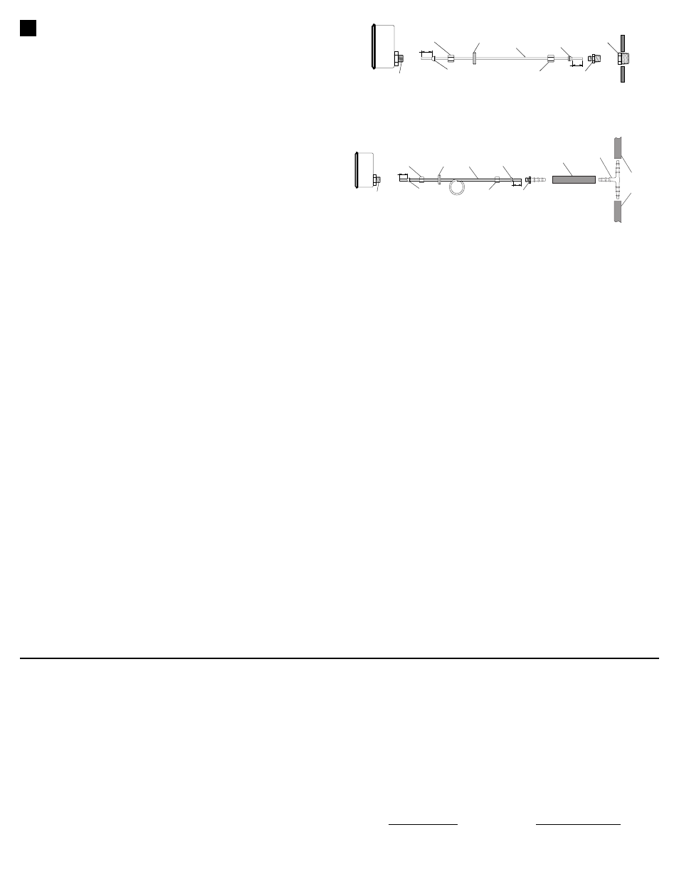
Option One - Intake Manifold Connection
See Figure 4 and follow the instructions below:
1. Remove plug from tapped hole on intake manifold and install 1/8" -
27 NPT or 1/4" - 18 NPT adapter, as required, in tapped hole.
NOTE: Additional adapters must be purchased separately.
2. Connect nylon tubing to the installed adapter using compression
sleeve and compression nut provided. Tighten compression nut
until tubing is secure.
Option Two - Existing Vacuum Line Connection
See Figure 5 and follow the instructions below:
1. Connect nylon tubing to the 5/16" (7,9 mm) vacuum nipple using
compression sleeve and compression nut provided. Tighten com-
pression nut until tubing is secure.
2. Insert vacuum nipple into one end of the 5/16" X 4" (7,9 mm X 10,2
cm) hose (provided); insert the vacuum "T" fitting into the other end
of the hose.
3. Cut the selected vacuum hose on the vehicle and install "T" fitting
in line with this hose. Use hose clamps (purchased separately) as
needed to secure "T" fitting.
FINISHING THE INSTALLATION
1. Secure tubing along its route to prevent damage from sharp edges,
moving parts or hot engine components.
2. Reconnect negative (-) battery cable. Start and run engine for
approximately 30 seconds and check gauge installation for leaks.
Tighten or reseal joints as needed and retest.
GROMMET
COMPRESSION
SLEEVE
COMPRESSION
NUT
COMPRESSION
NUT
COMPRESSION
SLEEVE
ADAPTER
*
*
USE TEFLON SEALING TAPE ON NOTED THREAD JOINTS.
NYLON
TUBING
INTAKE
MANIFOLD
1/8"
1/8"
GAUGE
PORT
*
TUBE
CONNECTOR
*
Figure 4. Boost/Vacuum Gauge - Intake Manifold Connection
The Manufacturer warrants to the original purchaser that this unit is free of defects in
materials and workmanship under normal use and maintenance for a period of one (1)
year from the date of original purchase. If the unit fails within the one (1) year period, it
will be repaired or replaced, at the Manufacturer's option, at no charge, when returned
prepaid to the Technical Service Center with Proof of Purchase. The sales receipt may
be used for this purpose. Installation labor is not covered under this warranty.
All replacement parts, whether new or re-manufactured, assume as their warranty
period for only the remaining time of this warranty. This warranty does not apply to
damage caused by improper use, accident, abuse, improper voltage, service, fire,
flood, lightning, or other acts of God, or if the product was altered or repaired by any-
one other than the Manufacturer's Technical Service Center. Consequential and inci-
dental damages are not recoverable under this warranty. Some states do not allow
the exclusion or limitation of incidental or consequential damages, so the above lim-
itation or exclusion may not apply to you.
This warranty gives you specific legal rights, and you may also have other rights,
which vary from state to state. No portion of this warranty may be copied or dupli-
cated without the expressed written permission from the Manufacturer.
Obtaining Warranty Service:
Products requiring service should be returned as follows:
1. Call the Technical Service Center to obtain a Return Reference Number:
USA & Canada = 1-800-544-4124
Other = 714-241-6805
2. Package the product carefully to prevent shipping damage
3. Include your name, return address, and a day contact phone
4. Enclose a copy of the dated sales receipt
5. Describe the problem
6. Ship prepaid to: Technical Service Center, 17291 Mt. Herrmann Street, Fountain
Valley, CA 92708 U.S.A.
Phone: 1-800-544-4124 or 714-241-6805 Fax: 714-432-7910
Web: www.iEQUUS.com
Email: [email protected]
LIMITED WARRANTY AND SERVICE PROCEDURES
OPTIONAL
GROMMET
COMPRESSION
SLEEVE
COMPRESSION
NUT
COMPRESSION
NUT
COMPRESSION
SLEEVE
VACUUM
NIPPLE
NYLON
TUBING
1/8"
1/8"
VACUUM
HOSE
FROM
MANIFOLD
HOSE 5/16" x 4"
GAUGE
PORT
*
VACUUM
TEE
*
*
USE TEFLON SEALING TAPE ON NOTED THREAD JOINTS.
Figure 5. Boost/Vacuum Gauge “T” Fitting Option Connection